![]()
[Home] [EISA .cfg Archive] [Chip set Encyclopedia]
Please note: this site has moved from
http://108.59.254.117/~mR_Slug/ to
http://66.113.161.23/~mR_Slug/. Please update any bookmarks.
![]()
[Home] [EISA .cfg Archive] [Chip set Encyclopedia]
Please note: this site has moved from
http://108.59.254.117/~mR_Slug/ to
http://66.113.161.23/~mR_Slug/. Please update any bookmarks.
Converting a NetVoyager LX-1022 (Astec A3x00) Thin Client to a routerPreface:I was looking to replace my pfsense router that is currently being powered by a dual Xeon (P4 era) 3.0GHz system. It's been very reliable, but is ridiculously overpowered for what I need. It also draws a considerable amount of current and is bulky. A bewildering choice really, it was supposed to be temporary. I asked in a forum about what the best thing to use for a router was and I got a variety of suggestions. Second-hand enterprise hardware, great but not low power. Adapted thin clients, and MiniITX based 1U servers. I initially went down the 1U server path and this is definitely an option, but the price kept going up. The motherboard, case and PSU seems to head towards £100, unless you have a 4U server or some other non-optimal solution. MiniITX boards were chosen because they are low power. In addition the features I was adding to it kept increasing, this was partly to off-set the high cost. I have a variety of vintage hardware, and a token-ring router made out of an old PC. So conglomerating this in the system, and possibly a FDDI connection would suit me well. At one point I decided that the best approach was to mount a thin client board inside a rack-mount case to give me a low-power system powered by a power-brick. Then have some PCIe-to-PCI bridge-boards to allow the mounting of Ethernet, Token-ring and FDDI adapters inside one giant case. The device was becoming monstrously labyrinthine! Configuration would also be a nightmare. So I decided to keep things simple and just build a device to do ONE thing. Ah feature-creep how obnoxiously persuasive you are. Main:Inspired by a few pages over at
http://www.parkytowers.me.uk.
I decided to have a go at converting one of these devices to a router. I
trawled thru the site and eBay looking for various different thin clients and
settled on this particular unit primarily because it was cheap (£12.50 inc
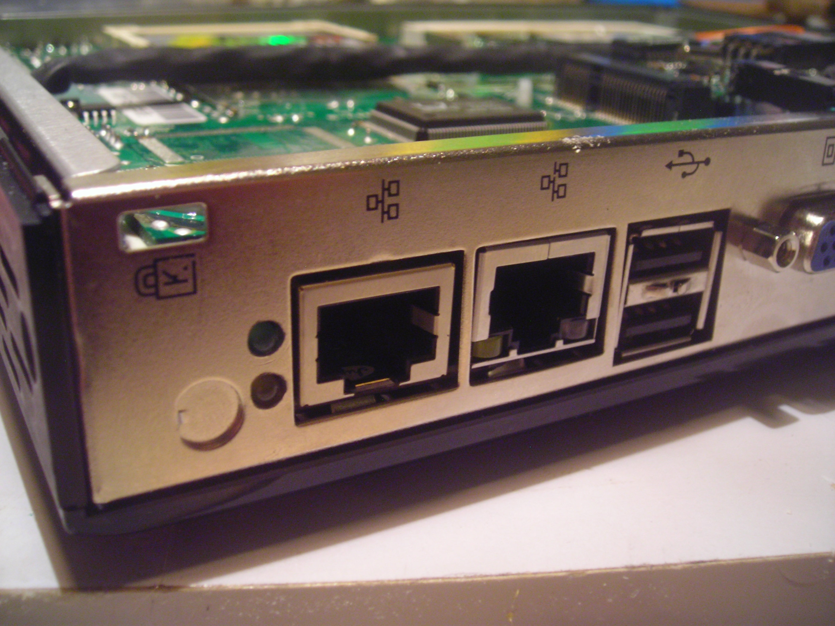
shipping), small (about 1U high, half width), and had a cutout for a second
Ethernet port.
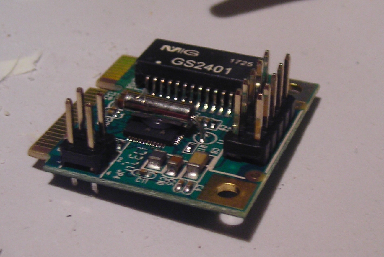
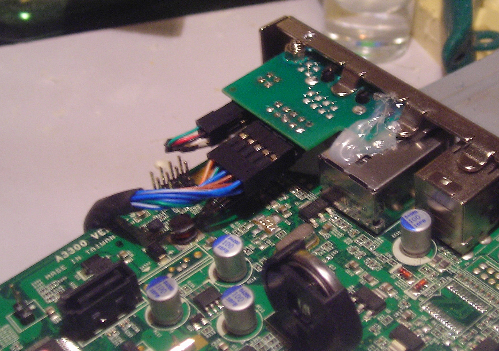
The large pin header is for the Ethernet connection and the small one is for the Ethernet lights. Awkwardly this would not fit within NetVoyager's case so I had to convert these to a right-angled version that I'd scavenged off an old broken HDD. There was also a problem that this card is a half-sized card, and the NetVoyager's mPCIe slot has a mounting screw for a full sized mPCIe card. There are adapters for a few pennies, but I decided to make my own out of some plastic.
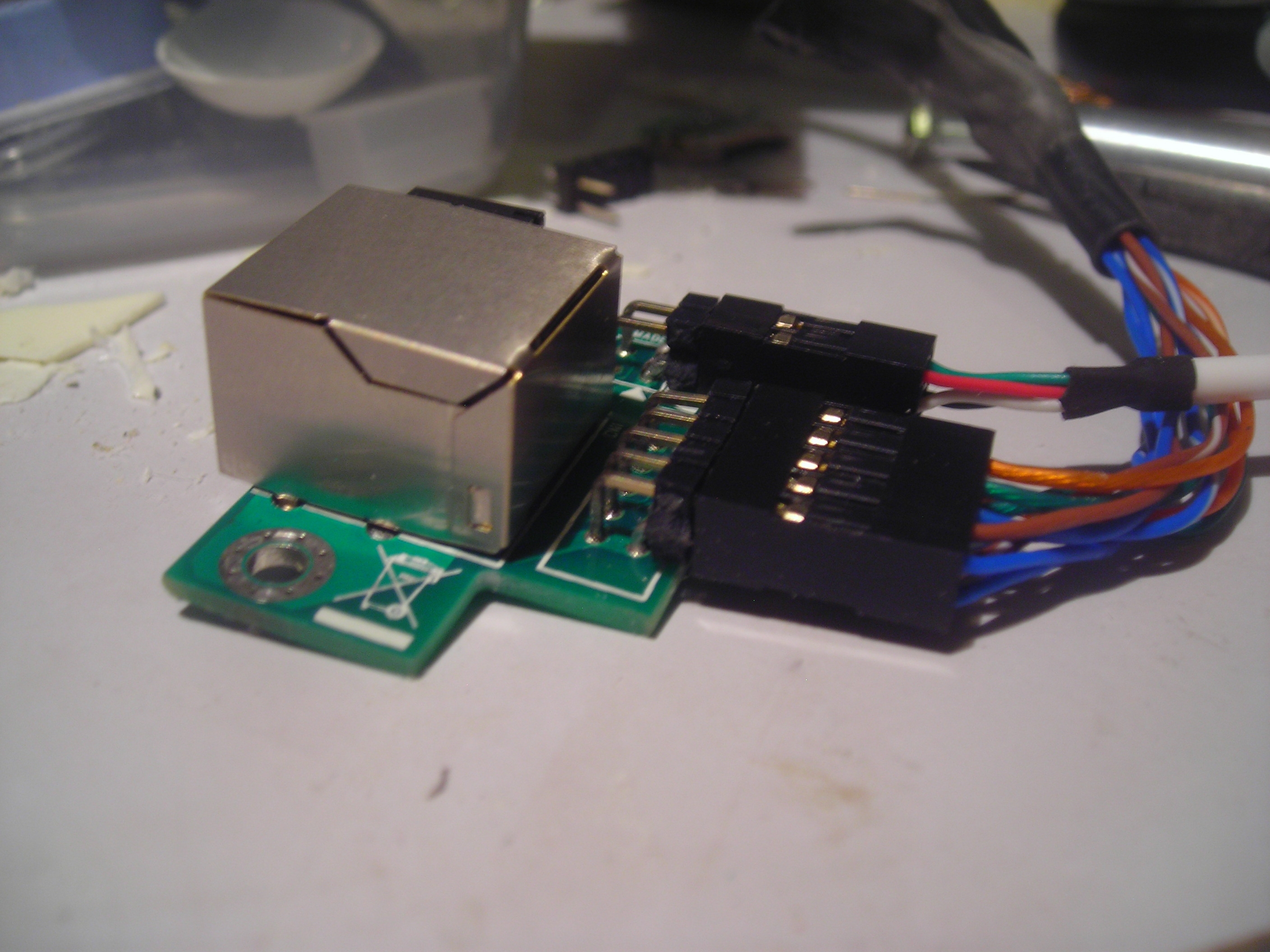
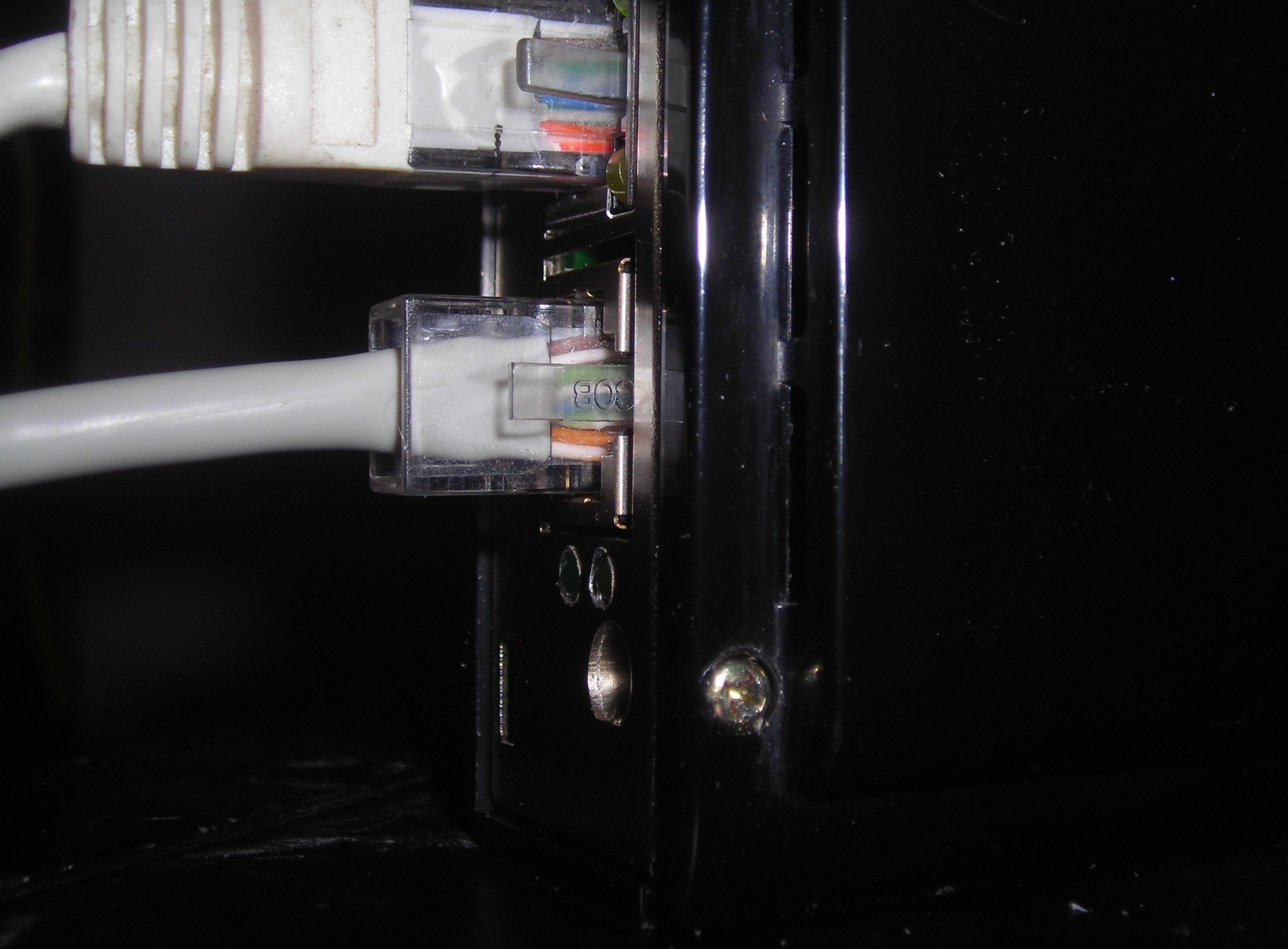
Now the Ethernet connector: Unfortunately the RJ45 connector I needed was impossible to find cheaply, or quickly. I'm sure Mouser etc would have one, but by the time you've factored in shipping, I usually end up spending £50 at one of these places to make it worth my while. eBay had some from China, but you had to buy 10, and it takes ages. So I looked at using the existing connector that was part of the Syba package. By pure luck I was able to cram this into the device. The PCB is on the opposite side to the connector in the NetVoyager. This allowed me to have the RJ45 slots in the same orientation. One additional annoyance is that the Syba connector does not have integrated LED's, so I had to drill 2 additional holes to allow these to poke thru the chassis. This fit perfectly, but now the pin-headers were a problem, requiring right-angle connectors:
Inside things look a little less professional. I just used hot-glue to hold everything in place. There is more glue between the motherboard and RJ45 connector on the small PCB. You can see this in the image:
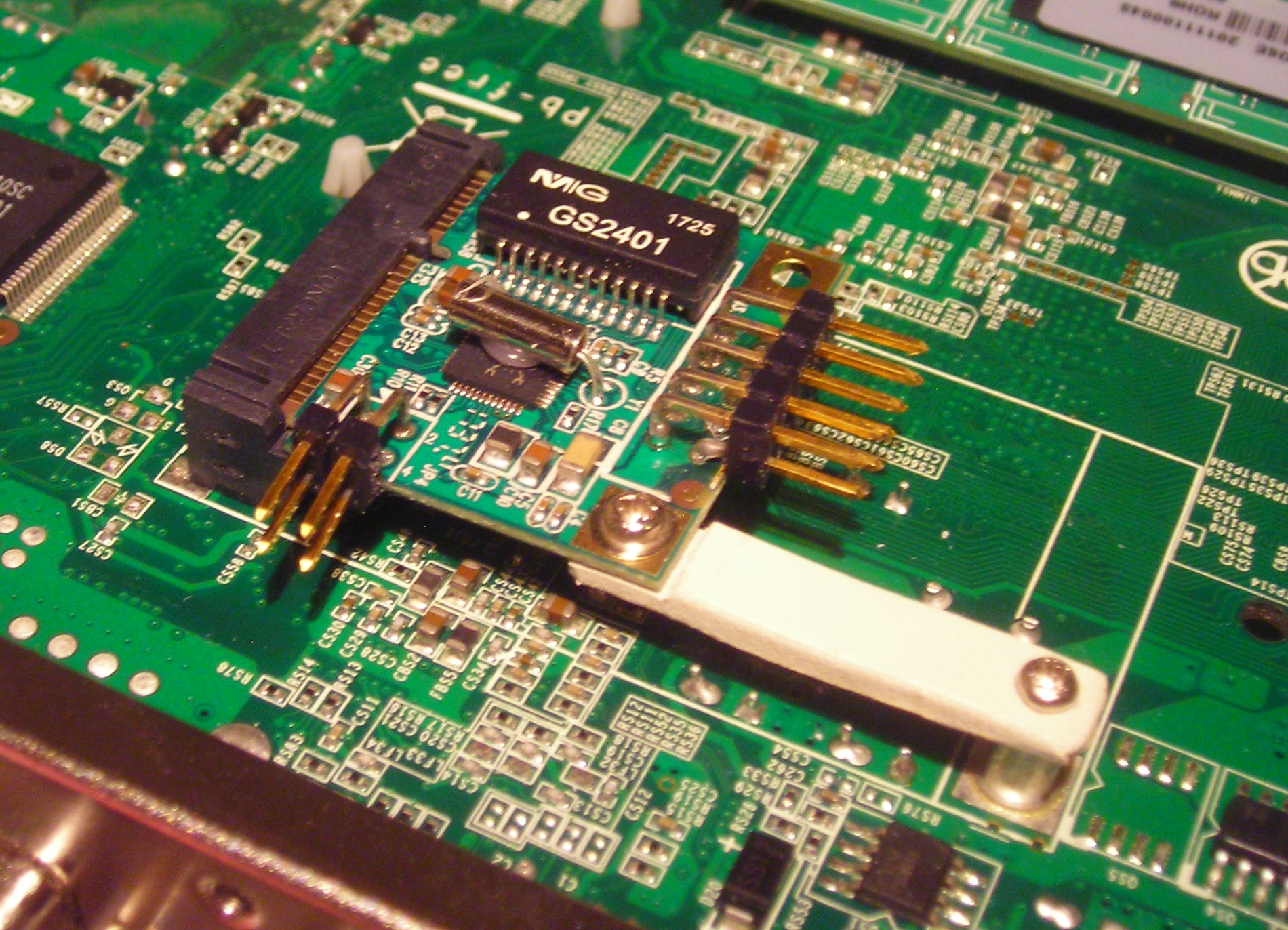
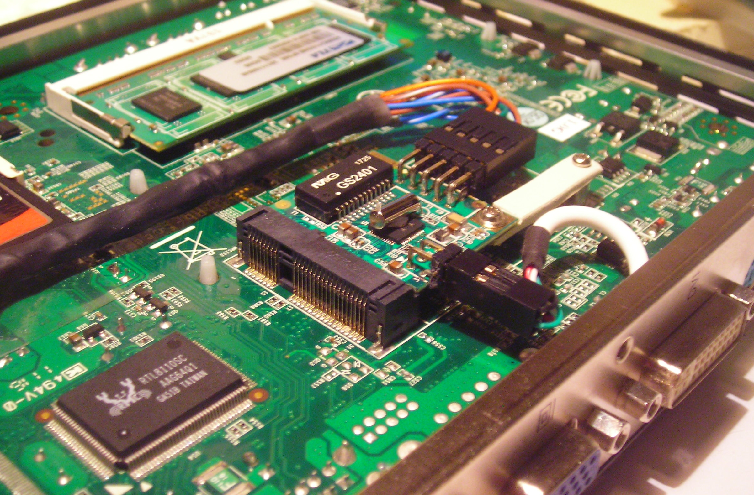
The inclusion of this additional PCB had another problem. It blocked a mounting hole on the motherboards PCB. The two halves of the case have plastic standoffs on either side of the PCB that keep the motherboard mounted in the correct place. For each corresponding pair of stand-offs a single screw goes thru one stand-off, thru the PCB and then into the other stand-off. This required me to cut out the plastic stand-off in this location. I had initially thought the 4 other pairs would have secured the case sufficiently however this was incorrect. So I added a small screw to secure the plastic case to the metal in this location. I had to do this on both sides. Below is an image of the screw and the mPCIe adapter installed and connected:
Conclusion:The device is nice and compact, and with a rack-ear attached to the side could probably be mounted in 1U. AFAIK, you could put two of these side by side. I haven't tried either yet. All in all it seems to work quite well, however it did require some modding of the components to get everything to fit. If you don't like soldering or "engineering" components to fit out of scrap you have lying around, I wouldn't recommend it. But, it does work. Using ~10-15W to do a task that was previously requiring 150W was the goal for this project, and that it does. So all in all it was a success. On the software side, this is just a pfsense CF-card install, nothing special. One got-ya was transferring the config from the old system to the new. The interfaces have to be redefined (easy), and there was a problem with the https cert. The cert issue results in the webConfig constantly saying it needs cookies to be enabled. The solution turned out to restart the webConfig from the console. |


(c) Copyright mR_Slug - All rights reserved