

| Item | Description | Item | Description | |
|---|---|---|---|---|
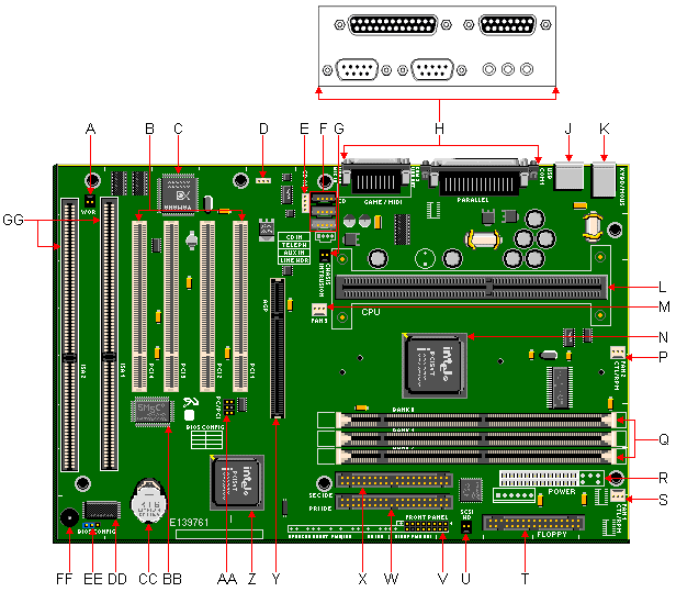
| A | Wake On Ring Connector | S | Fan 1 Connector | |
| B | PCI Slots | T | Floppy Connector | |
| C | YamahaSD1-L PCI Accelerator | U | SCSI HD Connector | |
| D | Wake On LAN Connector (Optional) | V | Front Panel Connectors | |
| E | CD Audio Connector | W | Primary IDE Connector | |
| F | CD-ROM Audio, Telephony & Aux. Line-In Connectors | X | Secondary IDE Connector | |
| G | Chassis Intrusion Connector | Y | AGP Port | |
| H | Rear Port Connectors | Z | 82371EB PIIX4E | |
| J | Dual USB Ports | AA | PC/PCI Connector | |
| K | PS/2 Keyboard & Mouse Ports | BB | SMC FDC37M707 Super I/O Controller | |
| L | SLOT1 SEC Cartridge Connector | CC | Battery | |
| M | Fan 3 Connector | DD | Flash BIOS | |
| N | 82443BX PCI AGP Controller (PAC) | EE | System Configuration Jumper Block (J8A1) | |
| P | Fan 2 Connector | FF | Piezo Speaker | |
| Q | DIMM sockets | GG | ISA Slots | |
| R | Power Supply Connector | |||
Jumpers
| Function | Jumper J8A1 | Configuration |
|---|---|---|
| Normal | The BIOS uses current configuration information and passwords for booting. | |
| Configure | After POST, CMOS Setup runs automatically. The maintenance menu is displayed. | |
| Recovery | The BIOS attempts to recover the BIOS information. A recovery diskette is required. |
Front Panel Connectors
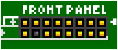
This motherboard has two possible configurations for the front panel connectors, a 1x19-pin header or a 2x9-pin header. The configuration is based on the type of case used.
| 1x19-Pin Header | 2x9-Pin Header | |
|---|---|---|
 |
 |
|
| The 1x19-pin header is intended for use in a case that utilizes individual connectors for each front panel function. | The 2x9-pin header is intended for use in a case that utilizes a single, keyed front panel connector. |