
| A female DB15 connector built-in on the motherboard. |
 |
| A female DB25 connector built-in on the motherboard. |
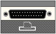 {ewc MVBMP2, ViewerBmp2, !db25port.bmp} {ewc MVBMP2, ViewerBmp2, !db25port.bmp} |
| A male DB9 connector built-in on the motherboard. |
 |
| A male DB9 connector built-in on the motherboard. |
|
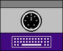
| A female 6-pin mini DIN connector built-in on the motherboard. |
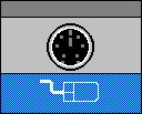 |
| A female 6-pin mini DIN connector built-in on the motherboard. |
 |
| This riser can accommodate the following expansion slots configuration: | |
| 4 X 4 Case | 2 ISA slots |
| 1 PCI slot | |
| 1 Combo PCI/ISA slot | |
| Mini Tower | 2 ISA slots |
| 2 PCI slots | |
| 1 Combo PCI/ISA slot | |
| This area is blank. It is reserved for a 20-pin connector normally referred to as the JMOD connector. |
 |
| These four chips make up the 2 MB video memory built-in on the motherboard. |
See Also: Video Upgrade Information U3H1: Cirrus Logic Video Chipset
| The Cirrus Logic GD-5446 video controller is soldered onto the motherboard. |
| J13 is a male 2 x 13-pin VESA feature connector allowing video to be routed through a video capture card or a PBTV card. |
 |
| J27 is a male 2 x 17-pin floppy drive connector. |
| Capable of supporting up to 2.88 MB capacity floppy drive |
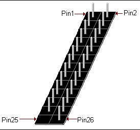
| This male 2 x 20-pin connector is the primary IDE interface. |
| BIOS supports for: |
| Type F DMA and AT API Devices |
| Logical Block Addressing (LBA) |
| Enhance CHS |
| Capable of supporting up to PIO Mode 4 |
| This male 2 x 20-pin connector is the secondary IDE interface. |
| BIOS supports for: |
| Type F DMA and AT API Devices |
| Logical Block Addressing (LBA) |
| Enhance CHS |
| Capable of supporting up to PIO Mode 4 |
| This 3V Lithium clip in battery is replaceable with a CR2032 battery |
| See Also: Battery Upgrade Information |
| Intel Pentium 75 MHz | Intel Pentium 133 MHz | |
| Intel Pentium 90 MHz | Intel Pentium 150 MHz | |
| Intel Pentium 100 Mhz | Intel Pentium 166 MHz | |
| Intel Pentium 120 Mhz | ||
| Uses the 320-pin Type 5 Zero Insertion Force (ZIF) CPU socket. | ||
| Not keyboard switchable. | ||
| Disable cache to slow down system. | ||
| Only on systems with a Type 7 Socket | ||
See Also: Processor Upgrade Information
| Socket Orientation: The socket closest to the Riser slot is J6F1, and to the right is J7F1. These two sockets make up the first bank (BANK 0). The next one over to the right is socket J7F2, and the right most socket is J7F3. These two sockets make up the second bank (BANK 1). This motherboard uses four vertical right key metal latch SIMM sockets. |
| See Also: |
| Ram Upgrade Information |
| This makes it possible for the BIOS to be upgraded via software rather than replacing the BIOS chip. |
See Also: Bios Upgrade Information |
| This motherboard may come configured with a CELP socket. This socket supports 256k COAST modules for upgrading the External Cache. If there is no CELP socket on-board |
| then the motherboard will be configured with 256k cache soldered on-board at locations |
| U2E1, U2E2, U3E1, U3E2, U2D1, U2D2, U3D1, U3D2. |
See Also: |
| Cache Upgrade Information |
 |
 |
 |
 |
 |
 |
| Pin | Signal |
| 1 | FANNEG |
| 2 | FANPWR |
The power supply provided with these systems has a two prong connector
designed for this connector. The connector is keyed so that the
power cable can not be connected here improperly. The function
of this connector is to receive 5 volts from the power supply
for use by the CPU fan. The CPU fan connects to J6A1. J6A1 receives
the 5 volts from the power cable connected to J8F1
 |
 |