This information was extracted from a Windows .hlp file, XX.HLP. Typographical errors have been left in this extracted version.
-mr_slug
Contents
Xtended Xpress Product History
Xxpress Help File Revision Summary
Xtended Xpress Product History
XX 15" Fab 6 Info
Baseboard History
XTENDED XPRESS SYSTEM REVISION SUMMARY
Driver / Country Kit History
XX-SERIES PROCESSOR MODULE REVISION SUMMARY
BIOS History
SCU History
Adaptec SCSI Driver History
XX 15" Fab 6 Info
In late Q2 1996 the Xtended Xpress 15" baseboard will be revised to Fab 6, currently the board is at Fab 5A.
Currently the most significant change to the XX 15" baseboard will be new PCXB ASICS which will improve performance and add PCI locking functionality which will also improve performance.
All blue wires will also be 'buried' to improve manufacturability.
Baseboard History
Product | PBA | Rev. | BIOS Level | ECU | Suggested BIOS/ECU | Date | Release Notes |
XX 15" | 633996 | -003 | Alpha | Alpha | 1.00.04.BG0 / 3.11.39 | 2/95 | Pre-production Fab 4' NOT SUPPORTED |
MG5XX15M0 | 634688 | -001 | Beta | Beta | 1.00.04.BG0 / 3.11.39 | 3/95 | Release 1 - Fab 5 LIMITED SUPPORT Bury PCEB_CMD# rework PCI config mech 2 conflict fan sence and chassis sw improvements NMI/SMI PAL update |
|
| -002 | 1.00.01.BG0 | 3.07.26 | 1.00.04.BG0 / 3.11.39 | 4/95 | Release 1 - Fab 5 LIMITED SUPPORT BIOS to 1.00.01.BG0 SCU overlay26 |
|
| -003 | 1.00.01.BG0 | 3.07.26 | 1.00.04.BG0 / 3.11.39 | 5/95 | Release 1 - Fab 5 LIMITED SUPPORT Floppy WP problem |
|
| -004 | 1.00.03.BG0 | 3.09.35 | 1.00.04.BG0 / 3.11.39 | 7/95 | Release 1 - Fab 5 LIMITED SUPPORT Hobbes keylock fix New Keyboard CNTL BIOS to 1.00.03 New PCEB ASIC to -401 SCU OVL 35 |
|
| -005 | 1.00.04.BG0 | 3.11.39 | same | 9/95 | Release 1 - Fab 5 LIMITED SUPPORT New version of BIOS / SCU |
MG5XX15M0R2 | 637919 | -001 | 1.00.01.BG0 | 3.07.26 | 1.00.04.BG0 / 3.11.39 | 4/95 | Release 2 - Fab 5A Board ID to 0x5 PCXB concurrency fix new version of PCXB ASICs Adaptec Rev "C" SCSI Change Hobbes Rst pull-up Remove cap for P6 support |
|
| -002 | 0.13.02.BG0 | 3.09.33 | 1.00.04.BG0 / 3.11.39 | 5/95 | Release 2 - Fab 5A PCI lock# mask Floppy WP problem BIOS to 0.13.02.BG0 |
|
| -003 | 1.00.02.BG0 | 3.09.33 | 1.00.04.BG0 / 3.11.39 | 6/95 | Release 2 - Fab 5A 75/50 Cyclops 0C problem fix Update BIOS Server Mgmt keylock issue |
|
| -004 | 1.00.03.BG0 | 3.09.35 | 1.00.04.BG0 / 3.11.39 | 9/95 | Release 2 - Fab 5A Keyboard CNTL update New BIOS New PCEB ASIC New SCU OVL 35 |
|
| -005 | 1.00.04.BG0 | 3.11.39 | same | 9/95 | Release 2 - Fab 5A New version of BIOS / SCU |
|
| -006 | 1.00.04.BG0 | 3.11.39 | same | 11/95 | Release 2 - Fab 5A Added pull-up resistors to ESC ASIC to correct boot problem. |
|
| -101 | 1.00.04.BG0 | 3.11.39 | same | 12/95 | Release 2 - Fab 5 prime Bury blue wires in new fab |
XX 12" |
|
|
|
|
|
|
|
| 636507 | -004 | 1.00.01.BH0 | 3.09.33 | 1.00.02.BH0 / 3.11.39 | 6/95 | Release 1 Product |
|
| -005 | 1.00.01.BH0 | 3.09.33 | 1.00.02.BH0 / 3.11.39 | 6/95 | Fixed Server Mgmt event logging with pull-up resistor. |
| 640607 | -001 | 1.00.02.BH0 | 3.09.35 | 1.00.02.BH0 / 3.11.39 | 7/95 | Release 2 Product
New PCXB Bridge chip set, B1 step fixes concurrency problems PCI lock# mask New Rev C SCSI Adaptec 7870 SCSI Controller Remove embeded concurrency fix Improved I/O riser connector Improved keyboard controller New BIOS
|
|
|
|
|
|
|
|
|
XTENDED XPRESS SYSTEM REVISION SUMMARY
Product | TA | REV. | Date | Release Notes | |||||
MG5XX15M0 | 634131 | 002 | 5/95 | Production Release | |||||
MG5XX15M32 | 624665 | 002 | 5/95 | Production Release | |||||
MG5XX15M0R2 | 640622 | 001 | 7/95 | Production Release | |||||
MG5XX15M32R2 | 640030 | 001 | 7/95 | Production Release | |||||
COLXX12M16R2 | 641083 | 001 | 7/95 | Production Release | |||||
MG5XX12M16R2 | 644543 | 001 | 9/95 | Production Release | |||||
MG5 Chassis | |||||||||
Top Assembly | 623662 | -006 | Production | ||||||
|
| -007 | New Front Panel | ||||||
|
| -008 | Improved LCD Can | ||||||
Front Panel PBA | 635025 | -004 | Production | ||||||
|
| -101 | Added NMI switch, bury blue wires | ||||||
Power Supply | 617604 | -006 | Production | ||||||
|
| -007 | Changes to improve yield at mfr. | ||||||
Hot-Swap SCSI PBA | 631574 | -002 | Production Level | ||||||
Country Kit | 640978 | -004 | Release 2 country kit. | ||||||
|
|
|
| ||||||
|
|
|
| ||||||
|
|
|
| ||||||
|
|
|
| ||||||
|
|
|
| ||||||
Driver / Country Kit History
Country Kit - Contents | |||||
Country Kit | 640978 | -004 | Top Assembly Part Number | ||
| 642009-001 | SCSI Drivers v 1.10S3 for SCO UNIX 3.2r4 & Unixware 1.x | |||
| 642010-001 | Adaptec SCSI Drivers v1.10S3 for Unixware 2.x | |||
| 642011-001 | Adaptec SCSI Drivers v1.10S3 for OS/2, Netware, Windows NT. | |||
| 636495-001 | EZ-SCSI Utility v3,11 for DOS | |||
| 640936-001 | Diagnostics v3.17 | |||
| 640938-001 | Diagnostics v3.17 Documentation | |||
| 634807-001 | Cirrus Logic video drivers v 1.43 | |||
| 637955-001 | HAL v1.4 for Windows NT v3.5 | |||
| 644116-001 | SCU v3.11 overlay 39 | |||
| 642279-002 | Landesk Server Control v 1.11 Disk 1 | |||
| 642280-002 | Landesk Server Control v 1.11 Disk 2 | |||
| 636069-002 | Manual for Landesk Server Control | |||
| 626791-002 | Manual, Xtended Xpress 15" Product Guide | |||
| 627538-002 | Manual, Adaptec SCSI | |||
|
|
| |||
|
|
| |||
|
|
|
| ||
XX-SERIES PROCESSOR MODULE REVISION SUMMARY
Product | PBA | Rev. | TA Number | Rev. | Date | Release Notes | ||||||||
75 MHz Pentium Processor Module |
|
|
|
|
|
|
| |||||||
XXCPUPP75 | 631020 | -003 | 632678 | -001 | 1/95 | Production Release | ||||||||
|
| -004 |
| -002 | 6/95 | Fused tantalum caps | ||||||||
90 MHz Pentium Processor Module |
|
|
|
|
|
|
| |||||||
XXCPUPP90 | 634313 | -001 | 625717 | -001 | 1/95 | Production Release | ||||||||
|
| -002 |
| -002 | 6/95 | Fused tantalum caps | ||||||||
|
| -003 |
| -003 | 9/95 | PLX EQ6600 Clock Driver | ||||||||
100 MHz Pentium Processor Module |
|
|
|
|
|
|
| |||||||
XXCPUPP100 | 634314 | -001 | 625718 | -001 | 1/95 | Production Release | ||||||||
|
| -002 |
| -002 | 6/95 | Fused tantalum caps | ||||||||
|
| -003 |
| -003 | 9/95 | PLX EQ6600 Clock Driver | ||||||||
100 MHz Dual-Pentium Processor Module |
|
|
|
|
|
|
| |||||||
XXCPU2XPP100C1 | 630214 | -101 | 630216 | -001 | 7/95 | Production Release | ||||||||
|
| -102 |
| -002 | 8/95 | Fix Two Module Lock-Up | ||||||||
|
| -103 |
| -003 | 8/95 | Fix Temp-Ramp Problem | ||||||||
|
| -201 |
| -004 | 9/95 | New Fab to Bury Blue Wires | ||||||||
|
| -202 |
| -005 | 10/95 | PLX EQ6600 Clock Driver | ||||||||
133 MHz Pentium Processor Module |
|
|
|
|
|
|
| |||||||
XXCPUPP133 | 641365 | -002 | 641380 | -002 | 8/95 | Production Release | ||||||||
|
| -003 |
| -003 | 9/95 | PLX EQ6600 Clock Driver | ||||||||
133 MHz Dual-Pentium Processor Module |
|
|
|
|
|
|
| |||||||
XXCPU2XPP133C1 | 640007 | -002 | 640008 | -001 | 7/95 | Production Release | ||||||||
|
| -003 |
| -002 | 8/95 | Fix Temp-Ramp Problem | ||||||||
|
| -101 |
| -003 | 9/95 | New Fab to Bury Blue Wires | ||||||||
|
| -102 |
| -004 | 10/95 | PLX EQ6600 Clock Driver | ||||||||
BIOS History
BIOS version 1.00.00.BG0, 1.00.01.BG0
BIOS version 1.00.02.BG0
BIOS version 1.00.03.BG0
BIOS version 1.00.04.BG0
BIOS version 1.00.00.BG0, 1.00.01.BG0
About This Release:
Procedure for flashing this Release:
Issues Resolved in this Release:
Features Added or Changed in this Release:
About This Release:
1. This is the production 1.0 release of BIOS version 1.00.00 and provides individual BIOS tailored for each specific XXpress platform:
1.00.00.BG0 Medusa (XX-15")
2. NOTE: AMISCU System Configuration Utility Disk, Release 3.07, OVL 00.25 or later should be used with this BIOS.
3. NOTE: When previous BIOS is Beta 1.5 or eariler Beta, OR Alpha 34 or eariler Alpha:
When FMUP is used to update the System BIOS you MUST clear NVRAM RAM.
NOTE: To clear CMOS RAM:
1. Allow the system to boot with the CMOS CLEAR switch in the CLEAR position.
2. Put the CMOS CLEAR jumper back to the normal position.
3. Reboot the machine.
Failure to follow this procedure can result in unpredictable behavior.
4. This BIOS operates with FAB 4, FAB 4 Prime and FAB 5. This BIOS is formally released with Fab 5. Fab 4 and Fab 4 prime boards will be supported as much as possible. However, be aware that certain conditions may require the user to upgrade to FAB 5.
5. IRQ12 is not available for any resource except the mouse. The System BIOS reserves the IRQ12 resource when a mouse is not detected.
6. IDE drives default to Standard CHS translation. Use the System BIOS Setup program or the SCU to re-configure the IDE sub-system if this mode is incorrect for your IDE drive configuration.
7. When either the <Space Bar> or <ESC> key is pressed during the POST Memory Test the display of the amount of system memory tested stops. The test continues in the background. Pressing the <Space Bar> or <ESC> key to terminate the memory test will be removed in the next BIOS release.
8. If the boot device is a Hard disk, and that hard disk is not initialized, but does contain the 55AAh boot signature, the system will hang on boot.
9. This BIOS release is in English only.
Procedure for flashing this Release:
1. Execute FMUP utility and select to update system BIOS into Flash. Then Select BIOS 1.00.00.BG0_
2. Enter Setup through <F1> and Check out and note the following:
a) Check the SYSTEM DATE for correct year.
b) Note the IDE settings in the HARD DISK menus.
The IDE TRANSLATION MODE default is Standard CHS.
If no IDE drive is installed, set the INITIALIZTION TIMEOUT to 0 seconds.
c) If running NT go into the ADVANCED CHIPSET CONFIGURATION and change the MPS TABLE VERSION to 1.4 (Pre-Approved).
d) Go to the SECURITY Menu and set the RESET AND POWER SWITCH LOCKING to Disable unless desired.
e) Press <F10> to Save and Exit the configuration.
3 Boot from the SCU diskette and ...
Note: When executing SCU from a floppy diskette, DOS V6.22 or later is required.
a) There is not initial Password so when the SCU prompts for a password, press <ESC> to bypass setting of passwords.
b) Copy both CFG and OVL files from any additional addin cards needed to the SCU floppy diskette.
c) If no CFG file exists for any ISA card to be inserted into system board preform the following steps:
1. Press <F9> Utilities and then Press <F7> to Define ISA BOARDS.
2. Fill in the ISA Board Definition Menu as appropriate.
3. Press <F10> to save definition.
d) From the Main mnu go to STEP 2 and add the appropriate EISA and or ISA cards as desired. Note for ISA configurations, Press INSERT twice.
When Finished addin cards, Press <ESC> to get to main menu.
e) From Main Menu go to STEP 3. THen Pres enter at the SYTEM BOARD entry.
For any changes that are required for the system board, press enter on the function item and then select the desired choice followed by the enter key.
Slow ISA cards require that the shadow RAM region that their ROM occupies be disabled.
Press <ESC> when finished with change with the SYSTEM BOARD.
Next pres Enter for each of the SLot Entries. For PCI devices also Check each of their current selected resource hy pressing <F6>.
When finished viewing all the Slot entries, PRess <F9> and then select GLOBAL RESOURCE MAP for viewing.
f) From Main Menu go to STEP 4 to Save and Exit.
4. If any problems occur in the above process, then clear NVRAM using the procedure noted above in the About This Release section, step 3. Then repeat steps 1 through 3.
Issues Resolved in this Release:
1. Beta 12 banner is removed. Release banner is inserted.
Features Added or Changed in this Release:
1. None.
BIOS version 1.00.02.BG0
About This Release:
Issues Resolved in this Release:
Features Added or Changed in this Release:
About This Release:
1. This is the Release 2 of this BIOS. It provides individual BIOS tailored for each specific XXpress platform:
1.00.02.BG0_ Medusa (XX-15")
2. NOTE: AMISCU System Configuration Utility Disk, Release 3.09, OVL 00.33 or later should be used with this BIOS.
3. NOTE: When booting for the first time after updating to this BIOS revision, several error log messages may appear on the screen. If this occurs please clear the error log prior to proceeding. Then reboot the system.
4. NOTE: When clearing CMOS RAM you MUST allow the system to boot with the CMOS CLEAR switch in the CLEAR position. Then put the CMOS CLEAR jumper back to the normal position and reboot the machine. Failure to follow this procedure can result in unpredictable behavior.
5. This BIOS supports FAB 4 Prime, FAB 5 and FAB 5A.
6. This BIOS is equivalent to revision 0.13.02.BG0_. Only the sign-on banner has been modified to reflect the Release 2 level. Revision 0.13.02.BG0_ was tested by the Intel Compatibility Lab.
7. Integrated Adaptec SCSI BIOS is V1.15s.
8. Integrated Cirrus CL-GD542X VGA BIOS is V1.41.
Issues Resolved in this Release:
Note that all items below should be verified.
1. DCS 1879: 100VG EISA + LS/AMI ECU can't agree on a legal mem. mapped address
2. DCS 1954: Memory Resize Post error logged at type 8h instead of type 7h
3. DCS 1995: SMI Logs event 10h (system limit exceeded) incorrectly
4. DCS 2124: Video BIOS defaulted to non-shadowed OVL 28
6. DCS 2134: BIOS does not clean unused memory after installing PCI SCSI BIOS
7. DCS xxxx: Server will hang on an SMI event if the ESC chip is closed
8. DCS 1269: Need to have error message for "Insufficient space for BIOS"
9. DCS 2183: POST errors are logged with length 9h instead of 0Ah
10. DCS 2180: Post Errors not logged when Pause F1 on Errors enabled
11. DCS 2181: ASR logged as type 11 followed by type 8 entry
12. DCS 1888: System Hangs if Hard disk is not initialized to boot
Features Added or Changed in this Release:
1. This BIOS supports FAB 4 Prime, FAB 5 and FAB 5A standard and customs.
BIOS version 1.00.03.BG0
About This Release:
Issues Resolved in this Release:
Features Added or Changed in this Release:
About This Release:
1. This is the Release 2 of this BIOS. It provides individual BIOS tailored for each specific XXpress platform:
1.00.03.BG0_ Medusa (XX-15")
2. NOTE: AMISCU System Configuration Utility Disk, Release 3.09, OVL 00.35 or later should be used with this BIOS.
3. NOTE: When booting for the first time after updating to this BIOS revision, several error log messages may appear on the screen. If this occurs please clear the error log prior to proceeding. Then reboot the system.
4. NOTE: When clearing CMOS RAM you MUST allow the system to boot with the CMOS CLEAR switch in the CLEAR position. Then put the CMOS CLEAR jumper back to the normal position and reboot the machine. Failure to follow this procedure can result in unpredictable behavior.
5. This BIOS supports FAB 4 Prime, FAB 5 and FAB 5A.
6. This BIOS is equivalent to revision 0.03.03.BG0_. Only the sign-on banner has been modified to reflect the Release 3 level. Revision 0.03.03.BG0_ was tested by the Intel Compatibility Lab.
7. Integrated Adaptec SCSI BIOS is V1.19s6.
8. Integrated Cirrus CL-GD542X VGA BIOS is V1.41.
9. This BIOS utilizes new Flash Tables. The FMUP diskette contains a special batch file that must be used to flash this BIOS into a ROM that contains a pre-release 3 version of a BG0_ System BIOS (BG0_BG0_.BAT):
1) Insert a copy of the FMUP disk into Drive A:
2) Type 'A:' to select drive A:
3) Type 'BG0_BG0_'
4) The System BIOS will be updated without further user intervention.
5) The System will automatically reboot with the new System BIOS.
6) Use the FMUP.EXE program to update this BIOS with later revisions of the BG0_ System BIOS.
10. The FMUP diskette also contains a special Autoexec.Bat batch file that must be used in the recovery of the System BIOS. Do not use a standard FMUP Autoexec.Bat file.
Issues Resolved in this Release:
1. Compatibility LAB tested as revision 0.03.03.BG0_.
2. D-2445 Eisa cards are now detected in slot 6
3. D1996 Hobbes keylock control is implemented in the System BIOS
4. D1949 32-bit EISA NVRAM access via INT15h is now supported
5. D2367 Add-in 787x cards are no longer disabled when on-board SCISI BIOS scan is disabled
6. D2041 PCIPOST test errors are no longer reported
7. D2321 Flash recovery with custom System BIOSs now supported
8. D2434 IRQ12 is not missasigned when mouse is not attached
9. D2413 Turbo/Deturbo fails on FAB 5A
10. D-2423 Error log now matches INT15h, Function 21H
11. Three mode floppy now works on Drive B:
12. D-2940 Extended CMOS RAM PAB bit (reg. 4A Bit 3) is now cleared on power-up
13. D2167 Cancel WB is now defaults to Autodetect
14. D2409 Cache size is now correctly reported for Twin Oaks
15. Intel 15H Function DA88H now returns correct extended memory size in a 16M system
16. User Binary scan function 0x40 now enabled.
Features Added or Changed in this Release:
1. This BIOS supports FAB 4 Prime, FAB 5 and FAB 5A standard and customs.
2. This BIOS includes SCSI CD ROM boot code.Three mode
3. Cancel Write Back is now set automatically. Users also have the option of disabling Cancel Write Back; however they cannot manually enable the feature
4. The user is no longer requested to press a key to continue when an error occurs and no keyboard is attached to the system
5. Custom BIOS support is implemented in this release due to updated Flash Tables
6. THE LCD display during POST has been modified. It now displays the BIOS version string on the second line of the display. The countdown codes now appear in the top left corner. This was done to prevent the BIOS version string from wrapping to the second LCD line.
BIOS version 1.00.04.BG0
About This Release:
Issues Resolved in this Release:
Features Added or Changed in this Release:
About This Release:
1. This is the Release 4 of this BIOS. It provides individual BIOS tailored for each specific XXpress platform:
1.00.04.BG0_ Medusa (XX-15")
This Bios is similar to Beta 4.03 with banner change to reflect Release 4.
2. NOTE: AMISCU System Configuration Utility Disk, Release 3.09, OVL 00.35 or later should be used with this BIOS.
3. NOTE: When booting for the first time after updating to this BIOS revision, several error log messages may appear on the screen. If this occurs please clear the error log prior to proceeding. Then reboot the system.
4. NOTE: When clearing CMOS RAM you MUST allow the system to boot with the CMOS CLEAR switch in the CLEAR position. Then put the CMOS CLEAR jumper back to the normal position and reboot the machine. Failure to follow this procedure can result in unpredictable behavior.
5. This BIOS supports FAB 4 Prime, FAB 5 and FAB 5A.
6. Integrated Adaptec SCSI BIOS is V1.19s6. (No CD-ROM Boot Support)
7. Integrated Cirrus CL-GD542X VGA BIOS is V1.41.
8. This BIOS utilizes new Flash Tables. The FMUP diskette contains a special batch file that must be used to flash this BIOS into a ROM that contains a pre-release 3 version of a BG0_ System BIOS (BG0_BG0_.BAT):
1) Insert a copy of the FMUP disk into Drive A:
2) Type 'A:' to select drive A:
3) Type 'BG0_BG0_'
4) The System BIOS will be updated without further user intervention.
5) The System will automatically reboot with the new System BIOS.
6) Use the FMUP.EXE program to update this BIOS with later revisions of the BG0_ System BIOS.
9. The FMUP diskette also contains a special Autoexec.Bat batch file that must be used in the recovery of the System BIOS. Do not use a standard FMUP Autoexec.Bat file.
Issues Resolved in this Release:
1. DCS #2301 DMA 7 is released, when no IDE is present in the System.
2. Release DCS #678 Fix for Netware spurious interrupt.
3. DCS #2536 Intel Specific Services test Passes.
4. DCS#2537 NSP Bios test Passes.
5. DCS#2535 133MHz Cyclops, speed detection corrected.
6. DCS#2566 Int-15 AH=88h returns correct memory size with memory hole.
7. DCS#2570 SCU displays proper memory configuration with memory hole.
8. DCS#2150 NVRAM is loaded with default values during CMOS clear.
9. DCS#1812 System reports CPU info as per Intel-15 services.
10. DCS#2501 NSPDIAG test passes.
11. DCS#2244 FMUP works when ESC chip is closed.
12. Fix: Post error 41 and 43 miss the slot number if they are not both displayed in one Post session.
Features Added or Changed in this Release:
1. Added Console Redirection feature.
2. Option added for disabling APIC at boot for Novell Netware spurious interrupt fix. This option should be used with great caution. This option when disabled makes the system Uniprocessor and will not work with MP operating system.
SCU History
Release Notes for AMI System Configuration Utility 3.11 and Overlay 00.39
Release Notes for AMI System Configuration Utility 3.21 and Overlay 1.11
Release Notes for AMI System Configuration Utility 3.11 and Overlay 00.39
About This Release:
Issues Resolved in this Release:
Features Added or Changed in this Release:
Outstanding issues:
Overlay Lite User's Guide
Main Menu for SCU 3.09, Overlay 00.35
About This Release:
1. This is the release of Overlay 00.39 and the AMI System Configuration Utility 3.11 for use on the following platforms:
Medusa (XX-15") -- int3190 (BG0)
Valcor (XX-12") -- int3180
Altair(ALTServer) -- int31A0
Sgt. Preston(Sgt. Preston) -- int31C0
2. NOTE: AMI System Configuration Utility 3.11 and Overlay 00.39 should only be used with the following BIOS versions (or more recent BIOS versions):
Platform First compatible BIOS Latest Compatible Release
Medusa (XX-15") Alpha 00.00.01 R1.00.03 / R1.00.04
Valcor (XX-12") Beta 0.01.03 R1.00.02
Altair(ALTServer) Release 1.00.04 R1.00.10
Sgt. Preston(Sgt. Preston) Alpha 00.00.16 none
AMISCU 3.07 and OVL 00.26 should be used for earlier BIOS versions.
Issues Resolved in this Release:
1. Slot numbers are now displayed for ISA adapter cards. (DCS #2711)
2. When errors occur during the configuration of the baseboard configuration (i.e. an invalid password) the system will return to the main menu instead of "hanging" the system. (DCS #2360)
3. Locking resources at a car-level granularity is supported for ISA and EISA adapter cards. (DCS #2256)
4. Adding or removing an EISA adapter card from the system only invalidates the particular slot that was modified preventing the loss of adapter card settings or configurations. (DCS #2426 & #2427)
5. An option to allow the restoration of the baseboard settings/ISA CMOS was added to the baseboard password menu. (DCS #2519)
6. All references to "Memory Above/Below 512M" were removed from platforms int31A0 and int3180. (DCS #2399)
7. Added chassis switch enable/disable option to the int3180 platform. (DCS #2506)
8. Added "Define ISA" option in the "Add and Remove Boards" option of the SCU.
9. Increased general reliability of memory and virtual memory handling routines eliminating various "Out of memory" conditions. (DCS #2560)
10. Synchronized BIOS Setup and SCU options for IDE Sectors/Block. (DCS #2231)
11. Corrected jumper displays for int31A0 platform to match the latest board fabs. (DCS #2476)
12. Provided new 7870CFG.EXE (SCSISelect Utility) to correspond to a new SCSI BIOS for platform int31A0. (DCS #2660)
13. Defined all ports/resources present in the System PnP Device Nodes in the System configuration files. (DCS #2196)
14. Added code to allow sharing of port resources. (DCS #2473)
15. Added "Posted Write Buffers" options for HP version of int3190 platform. (DCS #2567)
16. Changed text for "Processor Status" from "Pass/Fail" to "Failures Detected/No Failures Detected" to avoid implying the presence of a non-existent processor. (DCS #2390)
17. Removed code indicating a "fatal" error if configuration conflict occur with the system baseboard and an adapter card. (DCS #2561)
18. Changed "Automatic/Manual" labels on PCI and PnP configurations to "Current/Manual." (DCS #2563)
19. Added code to set certain defaults in ISA CMOS if a "clear CMOS" condition is detected. (DCS #2568)
20. Added warning message to indicate invalid password. (DCS #2569)
21. Added code to detect the BIOS version present on the system and perform certain functions if appropriate. (DCS #2504)
22. Added "Arbitration Mode" options for HP version on int3190 platform. (DCS #2571)
23. Fixed "On" text in jumper and software description tables to correctly align text. (DCS #2589)
Features Added or Changed in this Release:
1. Overlay Lite will be included with all AMI SCU releases starting with AMI SCU 3.09 until the issues forcing its use are resolved.
Outstanding issues:
1. The SCSI BIOS version information is not available in the System Information Log.
2. When configuring multiple EISA cards or EISA cards requiring large amount of memory for the CFG/OVL combination, the AMISCU may terminate abnormally with an "Out of memory, can not continue." error. This problem will be addressed in a future release of the AMISCU/OVL.
3. PCI video devices are not special cased resulting in a blank screen DCS #2198. If an EISA or ISA non-video device requests memory at C0000 it will receive this resource and a PCI video device will be relocated because it is scanned by the AMISCU last. Video should always be given precedence for this memory location.
4. IRQ 12 is always assigned to the Mouse and can not be freed for other resources.
5. ISA cards added in a previous configuration with the SCU may be reset to defaults upon subsequent configurations.
6. The system baseboard overlay may not display the correct physical parameters of an IDE drive when in "Customize" mode.
7. When attempting to load a configuration file from an OEM diskette a false "Configuration file contains syntax errors" error may occur. If the user experiences this problem, he/she should attempt to add the desired card a second time (immediately after the error message.) If the "syntax errors" message is displayed on the sencond try, the file has one or more invalid commands. If the card is successfully added or an unresolvable conflict is reported, the configuration file is error free and the appropriate results of the configuration will be displayed (either suesfull addition or unresolvable conflict.)
Overlay Lite User's Guide
AMI System Configuration Utility 3.09, Overlay 00.35 and "Overlay Lite"
Note: The following instructions shall also apply to the "Overlay Lite" utility supplied with subsequent versions of the SCU and OVL.
The AMI SCU operates in Real Mode and is limited to using the 640KB memory space associated with DOS. In some configurations, users of the PCI/EISA server systems may experience "Out of Memory" errors when attempting to configure certain combinations of adapter cards.
In the unlikely event of this error being seen , "Overlay Lite" has been developed. By implementing a paging scheme in the AMI SCU 3.08 overlay 00.31, the available amount of memory for add-in card OVL/CFG files dramatically doubled. However, even with 115K-130KB available for the add-in card's OVL/CFG files it is mathematically possible to produce system configurations to exceed this limit. The "Overlay Lite" program frees approximately 130KB of additional memory for use by ISA/EISA/PCI adapter card OVL/CFG files. This additional memory is useable by the elimination of the very large server baseboard overlay file. The consequences of eliminating the baseboard overlay is the effective "locking" of the baseboard's resources. Locking the baseboard's resources does not produce any immediate problems, but it does prevent the user from changing any of the choices provided by the standard AMISCU overlay. The use of "Overlay Lite" can reduce memory requirements for system configuration to an extent that virtually no EISA/ISA/PCI configuration will be affected by the 640KB memory limitation.
The AMI System Configuration Utility 3.09 Overlay 00.35 should be used on the following platforms:
XX-15" -- int3190
XX-12" -- int3180
ALTServer -- int31A0
AMI System Configuration Utility Overlay 00.35 should only be used with the following BIOS versions (or more recent BIOS versions):
Platform Compatible BIOS*
XX-15", Release 1 Alpha 00.00.01, 1.00.01 BG0
XX-15", Release 2 Beta 0.13.02, 1.00 02 BG0
XX-12" Beta 0.01.03, 1.00.01 BH0
ALTServer 1.00.04 BI0, 1.00.07 BI0
*AMISCU 3.07 and OVL 00.26 should be used for earlier BIOS versions.
This document provides easy-to-perform instructions, functional considerations, and some special features for the use with "Overlay Lite." The special features related to the AMISCU 3.09 Overlay 00.35 are implemented to assist sophisticated users to monitor available memory and determine when "Overlay Lite" should be used.
Main Menu for SCU 3.09, Overlay 00.35
Perform the following steps to obtain a working version of Overlay Lite:
1) Format and 'sys' a new diskette with DOS 6.22.
2) Copy the contents of the provided System Configuration Diskette onto the newly created bootable diskette.
3) Boot the server system using the diskette.
4) When the system boots, the user will be presented a main menu with a number of choices:
1. Execute AMISCU
2. Execute AMISCU (baseboard configuration only)
3. Execute AMISCU using the Overlay Lite
4. Execute SCSISelect (TM) Utility (int31A0/ALTServer baseboard only)
The user has ten seconds to make a selection or menu item (1) will be automatically selected.
In order to help our customers determine when memory problems might occur, the AMISCU 3.09 includes two new features:
� Pressing <CTRL-M> at the main menu will display the largest free memory block (this value is effectively the amount of free memory in the system.)
� Pressing <CTRL-F> at the main menu will toggle-on (or toggle-off) a dynamic memory meter that appears in the upper left-hand corner of the screen. This "gas gauge" meter will be erased at every screen update by the AMISCU and is sometimes covered up. Asking for "Help (F1)" will usually provide a menu that displays this meter without being "covered up" right away.
The <CTRL-M> and <CTRL-F> features are only available at the main menu.
Execute AMISCU Selection
The majority of system configurations should work without incident. By selecting this option, the AMISCU will automatically locate all EISA/PCI devices and configure them into the system per the Plug-N-Play and PCI specifications. If this is the first time the system has been configured after shipment or after a "clear NVRAM" the user should choose "Execute AMISCU." The vast majority of OEMs are not expected to ever have a problem during the configuration of ISA/EISA/PCI add-in cards when executing this selection. However, if "Out of Memory" errors occur, the user should reboot using the System Configuration Utility and choose either "Execute AMISCU (baseboard configuration only)" if this is the first time the system has been configured since shipment or a "clear NVRAM" or "Execute AMISCU Using the Overlay Lite" if the system has been successfully configured since the last "clear NVRAM" or initial receipt of the system.
Execute AMISCU (baseboard configuration only) Selection
The user should configure the baseboard as desired, save the configuration, exit the AMISCU, and reboot the system using the AMISCU diskette and choose Execute AMISCU Using the Overlay Lite. Note: choosing "Execute AMISCU (baseboard configuration only)" will result in the configuration of the baseboard only; the previous settings of any adapter cards will be lost.
Execute AMISCU Using the Overlay Lite Selection
If configuring the system through the "Execute AMISCU" selection is unsuccessful (i.e. "Out of Memory" errors), the user may with to execute "Overlay Lite". This option locks the system baseboard configuration and increases the available memory by eliminating the very large server baseboard overlay file. Locking the baseboard's resources does not produce any immediate problems, but it does prevent the user from changing any of the choices provided by the standard AMISCU baseboard overlay. Any future system configuration changes/additions/deletions must be performed using this selection. The total time to configure the system will be approximately 5 minutes in some cases. Note: "Execute AMISCU Using the Overlay Lite" will only provide a reliable configuration if either "Execute AMISCU" or "Execute AMISCU (baseboard configuration only)" has been run successfully since the last "clear NVRAM" or initial receipt of the system.
Execute SCSISelect(TM) Utility Selection
This option is only for use on the ALTServer system platform. This option was installed to select the onboard AIC-7870 fast/wide SCSI controller. The SCSISelect utility enables and configures the AIC-7870 SCSI controller on the ALTServer platform. By selecting this option on either Xtended Xpress system platforms, this action will either lock up the system or cause unpredictable results. The SCSISelect configuration menu can be enabled on either Xtended Xpress system platforms by pressing <CTRL-A> during system initialization.
Release Notes for AMI System Configuration Utility 3.21 and Overlay 1.11
About This Release:
Issues Resolved in this Release:
Features Added or Changed in this Release:
Future Enhancements:
About This Release:
1. This is the release of Overlay 1.11 and the AMI System Configuration Utility 3.21 for use on the following platforms:
Xxpress 15" (Medusa) -- int3190
2. NOTE: AMI System Configuration Utility 3.21 and Overlay 1.11 should only be used with the following BIOS versions (or more recent BIOS versions):
Platform First compatible BIOS Latest Compatible Release
Xxpress 15" (Medusa) Release 1.00.5 R1.00.5
AMISCU 3.20 and OVL 01.00 should be used for BIOS version R1.00.04.
Issues Resolved in this Release:
1. If all A/D Channels are set to disable and saved, the SCU will correctly save the settings but will reload settings correctly on the next run (previously would reset to defaults.) DCS #2219
2. CMOS bit definitions for location and disposition of Console Redirection is correct (previously, bit settings were incorrect.) DCS #2125 & DCS #2280
3. OVLs supporting multiple add-in cards are handled correctly (previously would cause .CFG error message and undetermined SCU operation.) DCS #2273
4. Help text was added to the A/D Channel Switch Menu and the ISA ROM Memory Shadow Options Menu to indicate 'SPACE' would toggle the selection. DCS #2357
5. Help for conversion between Kelvin and Celcius was corrected ('add' changed to 'subtract'.) DCS #2210
6. Text for 'Lock Toggle" button changed to 'ISA/EISA Lock Toggle' (DCS #2226)
7. SCU will recognize and display lockes on PCI cards (previously did not always recognize locks on PCI cards.) DCS #2286
8. Switch information was corrected for Switch S8C1. (DCS #2358)
Features Added or Changed in this Release:
1. This is the last release of the AMI SCU that will support Overlay Lite, the issues forcing its use have been resolved. Future releases of the AMI SCU will not include or necessarily be compatible with Overlay Lite.
2. starting with AMI SCU 3.09 until the issues forcing its use are resolved.
3. Additional help is provided for the 1M ISA hole at 15M.
4. Choice added to enable/disable System Error Detection. (DCS #2285)
5. Choice added to select CD-ROM boot image type (floppy vs. hard drive.) (DCS #2314)
6. Choice added to allow toggle of PCI locking. (DCS #2315)
Future Enhancements:
1. The SCSI BIOS version information is not available in the System Information Log. (DCS #2183)
2. PCI video devices are not special cased resulting in a blank screen DCS #2198. If an EISA or ISA non-video device requests memory at C0000 it will receive this resource and a PCI video device will be relocated because it is scanned by the AMISCU last. Video should always be given precedence for this memory location.
3. IRQ 12 is always assigned to the Mouse and can not be freed for other resources.
4. If himem.sys does not load, viewing help when editing functions in an adapter card or baseboard may result in an "Out of Memory" error.
5. On some versions of the BIOS, systems with 16M utilizing the 1M Hole display an incorrect amount of extended memory.
6. The AMI SCU must be run with DOS loaded high. Failure to load DOS high will result in an error message indicating an "XMS paging fault" has occurred and the configuration will not be saved correctly. If himem.sys is not loaded (thus preventing DOS from loading high) this problem will not occur but other problems relating to low memory and higher wait times will appear.
7. BIOS serial redirection does not support all keys used by the SCU. Some keys (F1-F12, arrows) may need to be programmed into the terminal emulation package being used by the user. Some keys (ctrl-char, backtab, alt-char, PgUp, PgDn, insert) are not supported at all and alternate keys must be used (i.e. multiple down arrows or tabs in place of PgDn, 'wrapping' through the choices instead of using backtab or PgUp, using tab to highlight a choice instead of using the control character hotkey.)
Adaptec SCSI Driver History
Product Identification: v1.10S3- Intel to v1.2S2-Intel
This document will cover changes made to the Intel Special versions of the 7800 Family Manager Set. Please see the "7800 Family Manager Set v1.20 Product Change Notice" for standard product changes/enhancements that have been incorporated into v1.2S2-Intel. These two documents will give a complete
� Fixed incorrect driver banner on the NetWare driver from 1.10S to 1.2S2
� Modified for Unixware 2.1 driver that reduces CPU utilization for a Comdex demo
� Unixware 1.1 and 2.0 driver fixes for an OEM's wide negotiation
� Use BIOS negotiated value for the SCSI parameter upon power-on for embedded designs
� Displays a single BIOS banner for supported devices
Product Identification: v1.19S6-Intel to 1.2S4-Intel
The Adaptec Hardware Supported by the 7800 Family BIOS Developers Kit v.12S4-Intel:
� AIC-7880
� AIC-7870
� AIC-7850
The standard product changes/enhancements have been incorporated into the 7800 Family BDK. The "Specials" for Intel are applicable for Intel only.
Standard Product functional changes for the 7800 Family BDK are:
� Added build option for AIC-7880 (UltraSCSI)
� Added multiple LUN support
� Increased LUN Support from 8 to 16
� Lowered SCSI BIOS initialization (load image) size to 32K
� Modified InitGeometry procedure to properly initialize LUN numbers
� Created new boot manager to allow users to specify boot device by both target ID and LUN
� Added option in SCSISelect to allow automatic configuration of SCSI bus termination
� Added support for SCAM level 1
� Enhanced Int13 extension functions for bootable CD-ROM
� Fixed mirroring of drives when 3 host adapters are active for bootable CD-ROM
� Created new 7800 BIOS Developers Kit "Technical Reference: to simplify and document the build options available to OEMs.
Changes/Enhancements for Intel Specials:
� Fixed compatibility issues of the system not supporting the extended BIOS area on the Trident motherboard under the AMI BIOS
� SCSI Select <F6> resets to Intel's defaults, rather than Adaptec's defaults
Changed interpretive logic to display "Ctrl A" message.
� Fixed sequencer code to address corner case write issue.
Xtended Xpress Errata
Release 2
Release- 2 Baseboard/System Configurations Supported
Limitations in the BIOS and SCU
Limitations with the XX15" Baseboard and Pentium Processor Modules
Limitations with SCSI Add-in Cards, Hard Drives and Drivers
Limitations with LAN Adapter Cards and Drivers
Limitations with Miscellaneous Add-in Cards and Drivers
Known Issues Specific to Microsoft Windows NT 3.5 and 3.51 Versions
Known Issues Specific to SCO UNIX
Known Issues Specific to Novell UnixWare 2.0
Known Issues Specific to IBM OS/2 and LAN Manager
Known Issues Specific to Novell NetWare versions 3.12 and 4.10
Known Issues Specific to DOS
Known Issues Specific to Solaris 2.4
Known Issues Specific to Banyan Vines
Release 2
| Release -1 Product | Release - 2 Product |
Baseboard (PBA number) | FAB 5 (637688-00x) | FAB 5A (637919-00x) |
ASIC Revision | PCXB-B0 stepping | PCXB-B1 stepping |
BIOS / SCU Revision | 1.00.01 BG0 / overlay 26 | 1.00.04 BG0 / overlay 39 |
Adaptec SCSI Revision | AIC-7870 rev. B | AIC-7870 rev. C |
* All products and corporate names may be trademarks of their respective companies.
Release- 2 Baseboard/System Configurations Supported
XX-Series CPU Modules |
| Add-in LAN Adapters | ||
� 100 MHz Pentium processor module in UP/MP modes � 90 MHz Pentium processor module in UP/MP modes � 75 MHz Pentium processor module in UP/MP modes � 100 MHz Dual Pentium processor in MP / Quad mode � 133 MHz Dual Pentium processor* in MP / Quad mode |
| � Intel EtherExpress PRO/100 � SMC 8432T/BT � AMD PCnet � Znyx ZX312 / ZX342 � 3COM 3C595 � Intel TokenExpress | ||
Add-in SCSI Adapters � Onboard AIC-7870 SCSI controllers � Adaptec AHA-2940, AHA-3940, and AHA 2740 cardsAdaptec AHA-2940, AHA-3940, and AHA2740 cards � Intel XXRAID4 PCI RAID card � Mylex DAC960P, DAC960PL , DAC960 RAID cards � DPT 2024, 3224/90, and 3224/90W RAID cards |
| Operating Systems � Novell NetWare 3.12 and 4.10 � Microsoft Windows NT version 3.5 and 3.5.1 � SCO UNIX V.3.2R4, V.3.2.R4 MPX, and SCO V3.2R5* � AT&T UNIX V.4.2 � IBM OS/2 2.11, 2.11SMP*, and 3.0 Warp � Novell UnixWare 2.01 � Solaris 2.4, 2.5* | ||
* These are future products which have not yet been released. Please contact the appropriate vendor for schedule and availability information. The operation of these new products will be subject to limitations as posted in future errata listings. | ||||
The following is a list of known errata divided into BIOS/SCU limitations, baseboard/CPU module limitations, SCSI/LAN adapter limitations, and eight different operating system specific issues. Many of these items are being worked by the various companies and in no way reflect that any adapter or operating system is any better than another. A full compatibility report is in progress to include the full breadth of ISA/EISA/PCI add-in cards tested. This report, titled "Xtended Xpress Final Compatibility Test Report Summary, can be found in the secure area of the Intel Applications BBS (916-356-3600 Folsom, CA and 44-793-496340 Swindon, England). Intel plans on continuing to increase the number of add-in cards and application software tested in the coming months. This will be dictated by the market directions, customer demand on specific products, and engineering resources.
Limitations in the BIOS and SCU
The AMI SCU release 3.11 overlay 39 should be used with this BIOS 1.00 04 BG0 version. Integrated Adaptec SCSI BIOS v1.20 and Cirrus CL-GD542x VGA BIOS v1.41 into the new 1.00.04 BG0 released BIOS. This version of BIOS and AMI SCU are supported on release-2 baseboard/systems only.
P2519 Restoring the SCU configuration from backup does not entirely restore all XX15" baseboard settings.
Solution: To be fixed in a future release of the BIOS/SCU.
P2222 Upon initialization, the user may see an "ECC Address Failure" message displayed the first time the ECC memory module is installed.
Solution: To be fixed in a future release of the BIOS/SCU. The message will be fixed to display the proper error message of "ECC memory resize error". In any event, the user can execute the SCU to clear this message and insure the proper memory sized is saved in the system configuration file.
P2802 The Xtended Xpress system does not attempt to re-read a diskette in Drive A: if the system was first started with a non-bootable diskette.
Solution: Insure a bootable diskette is installed upon power on. To be fixed in a future release of the BIOS/SCU.
P2808 The Intel AIP component is not properly configured for full EPP/ECP support across the parallel port on the XX15" baseboard.
Solution: To be fixed in a future release of the BIOS/SCU.
R1964 A complete printout of all SCU settings is not available to the user.
Solution: To be fixed in a future release of the BIOS/SCU.
------- BIOS update to 1.00.04 cannot be completed if using the standard autoexec.bat file on the FMUP diskette.
Solution: The user must execute the batch file BG0_BG0_.BAT located on the Flash Update diskette to upgrade the BIOS revision.
Limitations with the XX15" Baseboard and Pentium Processor Modules
--- There is no support for Xpress (X-Series) Intel486 or X-Series Pentium processor modules in the XX15" system.
R455 The software utility for the various Operating Systems to view ECC single-bit error logging information is required.
Solution: The utility for Netware 3.12/4.10 is available and ships with the standard XX15/MG system.. Utilities for UNIX and Microsoft Windows NT are also being worked on, but no formal scheduled date of completion has been released.
P2708 The Intel Diagnostics version 3.17 will fail specific tests when used with the newer FAB5A XX15" baseboard.
Solution: Intel is working on an updated diagnostic utility.
P2413 When trying to use the CTRL-ALT-(numeric keypad)-1 and CTRL-ALT-(numeric keypad)-2 for "Turbo and Deturbo" settings, the XX15" may not properly switch back and forth.
Solution: This is a low priority issue. Likely to be fixed in a future BIOS/SCU.
P2792 The Kinesis Model 120 Ergonomic keyboard will not be properly seen by the XX15" system.
Solution: To be fixed with a future keyboard controller BIOS.
R1024 During the simulation of all possible combinations of the PCI Lock (PLOCK#) signal, a possibility exists of PCI locked cycles not actually locking the target resource. The possibility exists of the operating system performing a locked cycle to memory on a PCI video card while concurrently an EISA master is attempting to access the ECC memory. A deadlock (system hang) would be the result of the failure mode. Intel has not duplicated this possible read-modify-write operation with current operating system tests, current PCI add-in cards, or specific test configurations.
Solution: The current FAB 5A contains embedded circuitry to greatly reduce the risk of this premature negation of PLOCK# of happening. The embedded circuitry is in place to comply to the PCI 2.1 specification concerning the first transaction of a lock operation being a read transaction. Intel considers this actual sequence of PCI and EISA signal events of occurring as being very low. The long term solution is to fix this anomaly in a future revision of the PCXB chip set.
----- The XX-Series Dual Pentium Processor module will require the 82493 Cache SRAM (C88) to be upgraded to improve noise immunity and increase silicon availability.
Solution: The changes have no impact on device functionality, operating conditions, timings, reliability, or any other specifications. The changes cannot be detected externally, and there is no restriction on mixing parts with or without these changes for use on the same system. To be implemented with a future enginnering change order (ECO) which will include the newer stepping (A-3) of the 82493 Cache SRAM.
----- The XX-Series Single and Dual Pentium Processor modules will propigate a data corruption error during an intense disk stress test when the internal temperature is less then 7C.
Solution: Intel Engineering has determined the root cause to be a diode internally in the INCA component which latches the incorrect data. At 10C (or greater) the internal diode does not exhibit this same characteristic. A fix will likely be implemented in the November, 1995 timeframe on the XX15" baseboard.
P1955 The Matsushita 5.25" floppy drive cannot be initialized correctly as Floppy B.
Solution: The Matsushita floppy drive requires 16mA drivers to correctly initialize and select the drive. The 82091 (AIP) component on the Xtended Xpress baseboard contains 12mA drivers. This is known errata concerning the 82091 AIP component and this particular floppy drive. Other 5.25" floppy drives have been tested and work with no errors.
Limitations with SCSI Add-in Cards, Hard Drives and Drivers
P1849 When using hard drives with the "disk cache bit" set to enabled with any SCSI disk controller in the Xtended Xpress system, Intel recommends to turn off the embedded disk cache circuitry in the hard drives to insure data integrity. Many disk controller manufacturers, disk drive manufacturers, and operating system manufacturers also recommend disabling the disk cache circuitry embedded on the hard drive if errors persist.
Solution: Contact the manufacturer of the hard drive in question for more details to determine a utility to view the setting and disable if appropriate. The manufacturer should also be contacted for the information on firmware upgrades, new product schedules, and other utilities which may affect performance and data integrity.
R1455 The PCI-based DPT 3224/90 or 3224/90W add-in disk controller cards cannot share the same IRQ as the onboard AIC-7870 SCSI controllers.
Solution: Both DPT and Adaptec have been contacted concerning the issue.
P1773 The DCP-286i and DCP/MUX ISA add-in cards fail their diagnostics. When the cards were executed in a system configuration, no errors occurred.
Solution: The manufacturer of the DCP cards were notified of this diagnostic anomaly. This is a known issue with high speed Pentium processors in other systems.
Limitations with LAN Adapter Cards and Drivers
R700 When more then two EtherExpress PRO/100 PCI LAN cards are installed in the XX15" system, the third (or fourth) Pro/100 LAN card may not be correctly recognized by the Netware, SCO UNIX, UnixWare, OS/2 or Windows NT operating systems.
Solution: Intel Network Services Division has been notified. New drivers for these operating systems with the PCI PeerBus found on the XX15" baseboard are available. Contact Intel NPD for more information on schedules, possible fixes, and general driver updates.
R973 The PCI-based EtherExpress PRO/100 gives a Power On Self Test (POST) error upon bootup; "0804 PCI ROM not found".
Solution: Intel Network Products Division has determined this error causes no performance implications, no configuration implications, or data integrity implications when used in the Xtended Xpress server platform. The Xtended Xpress system BIOS performs a scan for any ROM BIOS code and determines from an 55AAh signature, that the PRO/100 add-in card contains a ROM BIOS. In fact, the add-in card does not contain any ROM code. This error will likely be fixed in a future BIOS/SCU revision in the November, 1995 timeframe. The error could also be fixed by Intel NPD on the PRO/100 to correctly adhere to the PCI 2.1 specification concerning optional BIOS signatures. Contact Intel NPD for more information on schedules, possible fixes, and general driver updates.
P2575 The ISA-based Novell Token Ring 2000 gives a Power On Self Test (POST) error upon bootup; "0805 Insufficient memory in shadow PCI ROM".
Solution: The Novell Network Division has been notified. The user can disable the AIC-7870 SCSI-B BIOS scan or change the address where the TR2000 add-in card contains memory. Contact Novell for more information on schedules, possible fixes, and general driver updates.
R1885 The EISA-based Speicalix SIO gives a Power On Self Test (POST) error upon bootup; "0805 Insufficient memory in shadow PCI ROM".
Solution: The manufacturer of the Speicalix add-in card has been notified. The user can disable the AIC-7870 SCSI-B BIOS scan or change the address where the Specialix add-in card contains memory. Contact the add-in card vendor for more information on schedules, possible fixes, and general driver updates.
P2801 The DigiBoard C/X add-in card is not allowed to share certain memoy ranges with other DigiBoard C/X add-in cards already configured in the XX15" server system.
Solution: DigiBoard and Intel are investigating this issue. This will likely be fixed in a future BIOS/SCU.
R2026 The PCI-based EtherExpress PRO/100, 3COM 3C595, and IBM LAN Streamer give a Power On Self Test (POST) error upon bootup; "0804 PCI ROM not found".
Solution: Each manufacturer has been notified. Each add-in card sends a PCI configuration header to the XX15" upon power up which signals a add-in card ROM BIOS is present, when in fact there is no ROM BIOS code on the card. The Intel BIOS engineering group is confident the add-in cards are not adhering to the PCI 2.1 specification concerning the "ROM BIOS Enable" bit and the BIOS "55AAh" signature sequence. Contact the add-in card manufacturer for more information on schedules, possible fixes, and general driver updates.
R2027 The PCI-based IBM LAN Streamer gives a Power On Self Test (POST) error upon bootup; "0803 Shadow of PCI ROM failed".
Solution: IBM has been notified. The ROM BIOS signature sequence performed by the Intel system BIOS is believed to be fully PCI 2.1 compliant. Contact IBM for more information on schedules, possible fixes, and general driver updates.
R1891 The PCI-based IBM Token Ring add-in card causes an NMI at POST when the Intel EtherExpress PRO/100 add-in card is also installed.
Solution: IBM and Intel Networks Products Division have been notified. If the user removes either the IBM or Intel LAN add-in card, there is no NMI reported to the XX15" system. If the user installs the IBM add-in into the PCI P0-3 slot and the Intel add-in into PCI P0-2 slot, there is no NMI reported to the XX15" system.
P1782 Insure that the Intel TokenExpress32 LAN card is installed before any other EISA add-in card. If the TokenExpress32 card is not the first card scanned, the SCU hangs and displays this message: "performing syntax check on !INT1202.CFG".
Solution: Intel NPD has been notified of this issue. To avoid the problem, insure that the TokenExpress32 card is the first EISA card scanned in the system.
Limitations with Miscellaneous Add-in Cards and Drivers
---- Video cards are not supported in the PCI-1 PeerBus structure. This is due to the PCI Specification 2.1 standard which states video memory must be scanned in the first (PCI-0) bus structure only.
P2800 When an ISA-based add-in card is installed into the Xtended Xpress baseboard which requires a 64KB contiguous block of memory starting at D0000h, the add-in may not be properly recognized.
Solution: The onboard AIC-7870 SCSI BIOS (when used as bootable devices) require 48KB of space starting at C8000h. The user may disable the AIC-7870 SCSI controllers and not utilizing them with bootable SCSI hard drives. Adding a EISA/PCI add-in card as the bootable device will insure the ISA add-in card gets the entire 64KB block required. Intel recommends utilizing newer add-in card technology which does not impose such limitations on the high-performance server system.
R1890 The XXRAID4 firmware version 230PL will cause all the yellow fault LED lights to reamin lit when used with the XX15/MG system platform.
Solution: To be fixed with a newer version of the XXRAID4 firmware.
Known Issues Specific to Microsoft Windows NT 3.5 and 3.51 Versions
P1481 When NT 3.5 converts from a FAT to NTFS file system, the operating system fails to send a "flush" command to any SCSI controller used in the system. This is a known Microsoft Windows NT anomaly. During installation, the operating system displays a message that tells the user to press any key to reboot the system to continue the installation process. By not sending a "flush" command at this time, the operating system assumes all data has been written from the disk controller to the hard drive(s), when in fact that action has not occurred. The problem was originally reported on any SCSI disk controller with disk cache on the add-in board, but it has also been seen with other non-caching disk controllers.
Solution: Wait 15-30 seconds after seeing this message "press any key to reboot the system...." before continuing with the installation process. This is a known Microsoft Windows NT 3.5 anomaly.
P2275 When using an IDE CD-ROM to install Windows NT 3.5 or 3.51 to an IDE drive, the installation process will fail.
Solution: The issue is currently under investigation.
P2841 Multiple Olicom PCI Token Ring adapters are not recognized by Windows NT 3.5 or 3.51.
Solution: Olicom and Intel are investigating this issue. Contact Olicom for the latest drivers for use with Microsoft Windows NT with the Olicom family of LAN adapters.
P2847 The DEC PCI 21050 bridge component is integrated on the SMC 8434, AHA-3940, and Zynx 315 PCI add-in cards and will not be correctly recognized with Windows NT 3.51 when installed in the XX15/MG system platform.
Solution: Intel and Microsoft are investigating this issue. The solution will likely be in the MP HAL code or in a future XX15" BIOS/SCU.
P2303 When using the Cogent EM946, SMC 8434, or AHA-3940W PCI add-in card controllers which utilize the DEC PCI 21050 bridge controller, Windows NT may not recognize the add-in card.
Solution: Microsoft has incorporated a newer HAL for MP 1.4 - compliant systems and updated drivers in the released version 3.51 of Windows NT.
R669 With the onboard Cirrus 5424 and two XX-Series Pentium processor modules, the Windows NT 3.5 "WinClock" graphics frame is corrupted with running two winclocks.
Solution: Cirrus Logic and Intel will be testing updated video drivers.
R1008 When using the ISA-based SMC 8115 Token-Ring adapter, the card fails to be initialized properly.
Solution: SMC has been notified. Contact SMC for the drivers which are released for the ISA-based 8115 Token-Ring card.
P2539 Each time a CD is removed/inserted into the CD-ROM drive, Windows NT 3.5 & 3.51 enters a log entry concerning an error on the AIC-7870 SCSI controller.
Solution: Adaptec is aware of the anomoly and will update the SCSI driver.
Known Issues Specific to SCO UNIX
P1844 When installing SCO UNIX ODT 3.0 onto a hard drive attached to SCSI-B channel, this error message appears: "alad driver cannot be opened". The onboard SCSI-B controller cannot be used as the boot device on SCO UNIX according to Santa Cruz Operations, Inc.
Solution: The installation process can be completed with an AHA-2940 add-in card or by using the onboard SCSI-A channel.
P2907 When trying to install SCO Release 5 beta using the DPT 3224/90W PCI add-in controller in PCI slot P2-1, the installation cannot be completed.
Solution: DPT and SCO have been notified of this anomoly.
P2782 The DPT 3224/90W PCI add-in controller and onboard AIC-7870 SCSI disk controller cannot share the same interrupt (IRQ).
Solution: DPT has been notified of this anomoly.
P2613 SCO UNIX ODT 3.0 cannot be installed onto Fast/Wide hard drives when the AIC-7870 SCSI controller settings are in the negotiate narrow mode.
Solution: Contact Seagate for a new version of firmware to fix this anomoly.
Known Issues Specific to Novell UnixWare 2.01
P1904 UnixWare 2.01 does not recognize the PS/2 mouse when installed in the upper (top) PS/2 port, although the keyboard is recognized in either PS/2 port on the XX15" server baseboard.
Solution: Place the PS/2 mouse in the lower port. Then both the mouse and keyboard are recognized by the UnixWare operating system. Novell has been notified of this anomaly.
P2203 When executing a disk stress test, along with three (or more) disk controllers, data corruption will occur after approximately 12 hours.
Solution: Novell and Intel are working on this issue. Many configurations using single or dual disk controllers and various hard drives have been performed with no errors.
P2024 When operating the Intel PRO/100 LAN card in the PCI1-1 or PCI1-2 slots, UnixWare 2.01 will panic and fault.
Solution: Intel Network Service Division and Novell are working on this issue. The current configuration which works is to insure the Intel PRO/100 LAN card is located in either PCI0 slot 1 or slot 2.
P2377 When operating the AMD PCNet LAN card, UnixWare 2.01 will log an excessive amount of log messages.
Solution: The AMD LAN division has been notified of this behavior.
Known Issues Specific to IBM OS/2 and LAN Manager
P1563 The SMC 8432T PCI LAN adapter fails to be recognized by the OS/2 2.11SMP operating system.
Solution: SMC has been notified, and they working on the drivers for OS/2 at the time of this writing.
P2168 When performing a moderate network stress test with one LAN card, a trap message will appear between 30-60 minutes. The test involves copying files between two DOS clients and one OS/2 client. The LAN cards used were the Zynx 342 or the Intel PRO/100.
Solution: IBM and Intel are working on this issue.
P2049 OS/2 2.11SMP scans the PCI bus when determining the bootable C: drive before scanning for any bootable EISA bus devices. This scan order is different then OS/2 3.0 Warp and other available operating systems. A system lockup will occur at boot-up, if hard drives are connected on both EISA and PCI bus structures. The system BIOS will assume the EISA hard drive is the bootable device while OS/2 2.11SMP assumes the bootable device to be on the PCI hard drive.
Solution: IBM has been contacted and is working on service pack to fix this anomaly. Contact IBM for information concerning the service pack existence, schedule of a possible fix, and any other errata concerning OS/2 2.11SMP.
P2153 OS/2 2.11, 2.11SMP and 3.0 Warp all display an icon for Floppy drive B: in the DRIVES folder even when there is no floppy B: device in the Xtended Xpress server system.
Solution: IBM is aware of the anomaly. If the icon is invoked, the object will access the floppy drive A: and will not cause a system lockup. Contact IBM for information concerning the service pack existence, schedule of a possible fix, and any other errata concerning OS/2 2.11SMP.
P2697 OS/2 2.11SMP will not execute properly in a moderate network stress test with the XX-Series dual Pentium Processor module.
Solution: Intel and IBM are investigating this anomoly.
Known Issues Specific to Novell NetWare versions 3.12 and 4.10
P2622 The user must load ASPI8DOS.SYS before any other file in the CONFIG.SYS file.
Solution: To be fixed with a new AIC-7870 SCSI BIOS and associated drivers.
P2621 The user is unable to load any module after AIC7870.DSK is loaded. After loading the AIC7870.DSK, the next module being loaded will display "invalid load format" error.
Solution: To be fixed with a new AIC-7870 SCSI BIOS and associated drivers. The user can re-load the module again and the correct loading procedure will be performed.
P2578 With one (or two) XX-Series dual Pentium Processor module installed, the XX15" server system will not operate properly with Novell 3.12 or 4.10 versions.
Solution: Use one XX-Series single Pentium Processor module since Novell is unable to recognize a SMP-ready server architecture at this time. Intel and Novell do not support dual processor configurations with current versions of Novell 3.12 and 4.10. Contact Novell for any scheduling information on the Netware SMP version.
Known Issues Specific to DOS
R579 A customized version of DOS 5.0-J cannot execute a program larger then 10 KB from a 3-mode or 2-mode floppy drive when connected to the XX15" server system. MS-DOS 5.0, 6.20, 6.21, 6.22; DR DOS 6.21, 6.24; and Japanese DOS 6.20V do not display the problem.
Solution: This anomoly will likely be fixed in a future release of the BIOS/SCU.
R1937 The MS-DOS 5.0 and DOS 5.0-J himem.sys is incompatible with the AMI/Intel SCU 3.11 overlay 39 executable.
Solution: A memory manager is required for use with the AMI/Intel System Configuration Utility. The standard himem.sys program with MS-DOS 5.0 and DOS 5.0-J contains known errata which results in erratic behavior with used with the SCU. The himem.sys program sent with MS-DOS 6.20, 6.21, 6.22; DR DOS 6.21, 6.24; and Japanese DOS 6.20V is tested and support for used with the AMI/Intel SCU. This anomoly will likely not be fixed in a future release of the BIOS/SCU since himem.sys is upgradable through the DOS manufacturer.
Known Issues Specific to Solaris 2.4
Solaris 2.4 has not been fully tested in the Xtended Xpress server system.
P2743 Solaris 2.4 will lockup right before the build to perform the /devices directories when booting the kernel.
Solution: This anomoly is being worked on by Intel and SunSoft. Solaris 2.4 (driver update 7) with the kernel patch version 12 is currently be tested. Another patch version of /kernel/mach/pcplusmp after installation is also being tested. Contact SunSoft for availability of any updated drivers, scheduled kernel updates, and kernel patches.
Known Issues Specific to Banyan Vines
Banyan Vines 5.53 (6) is supported and certified in the Xtended Xpress server system.
P2095 The ISA-based Banyan ICA card cannot be used in the Xtended Xpress system with more then 16MB of memory installed.
Solution: The memory hole between 15MB and 16MB selectable in the SCU is not compatible with the Banyan ICA card addressing scheme. This issue will be fixed in a future BIOS/SCU revision.
P2470 The IBM 16/4 ISA-based token ring fails to properly intialize when installed in the XX15" server system.
Solution: Intel and Banyan are investigating this anomoly.
P2578 With one (or two) XX-Series dual Pentium Processor module installed, the XX15" server system will not operate properly with Banyan Vines 5.53 and 6.0 versions.
Solution: Use one XX-Series single Pentium Processor module since Banyan is unable to recognize a SMP-ready server architecture at this time. Intel and Banyan do not support dual processor configurations with current versions of Banyan Vines. Contact Banyan for any scheduling information on the Banyan Vines MP version.
Technical Product Summary
System Architecture
Jumpers
Baseboard Components
Board Resource Maps
CPU Module Information
Chassis
Hot Swap Drive Bay Configuration
System Architecture
Xtended Xpress Scalable Architecture
The Xtended Xpress Bus Interface is a 64-bit version of the 32-bit Xpress Bus Interface.
Two separate PCI channels are implemented to maximize system performance.
Jumpers
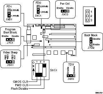
Figure Error! Reference source not found.-1. Switch and Jumpers
J4H1Test development vehicle (TDV)
J6A1Video sleep (starting addresses)
J7C1Program boot block ( BIOS protect/write)
J7D2Boot block (BIOS recovery)
J9C3PWR CTRL (power control)
J9B1FD1 (floppy drive 1)
J9C1FD0 (floppy drive 0)
S8C1Configuration switch
Related Topics:
Configuration Switch S8C1
Configuration Jumpers
Configuration Switch S8C1
The dip switch (Figure Error! Reference source not found.-Error! Bookmark not defined.) on the system board contains three switches. To change a setting, slide the switch to the desired position.
Table Error! Reference source not found.-1. Switch S8C1
Switch | Position | Function |
S8C1-1 | On | Clear CMOS |
S8C1-2 | On | Clear password |
S8C1-3 | On* | Enable flash write |
* Factory default setting.
Related Topics:
CMOS S8C1-1
Password S8C1-2
Flash Memory S8C1-3
CMOS S8C1-1
Setting this switch to ON clears CMOS sets it and the real-time clock (RTC) to the manufacturing defaults during system reset. Setting it to OFF preserves the settings during system reset.
To reset the system's CMOS and RTC chip to factory default values, do this:
1. Observe the precautions in Error! Reference source not found. on page Error! Reference source not found.-Error! Bookmark not defined..
2. Remove the side cover and ECC memory modules as described in Chapter 4, "Taking Your System Apart."
3. Slide the switch to ON; replace the ECC memory modules and side cover, and connect the power cord to the system.
4. Turn the system on, and wait for POST to complete. This automatically reprograms the CMOS and RTC to their default settings.
5. Turn the system off, disconnect the power cord from the system, and remove the side cover and ECC memory modules.
6. Slide the switch to OFF; replace the ECC memory modules and side cover, and connect the power cord to the system.
7. After resetting the CMOS, run the CU to configure your system. For information on running the CU, see Chapter 3, "Configuring Your Server."
Password S8C1-2
Setting this switch to ON clears the password when the system is reset. Setting it to OFF lets you enter a password.
To clear and enter your password, do this:
1. Observe the precautions in Error! Reference source not found. on page Error! Reference source not found.-Error! Bookmark not defined..
2. Remove the side cover and ECC memory modules as described in Chapter 4, "Taking Your System Apart."
3. Slide the switch to ON to clear your system password.
4. Replace the ECC memory modules and side cover, and connect the power cord to the system.
5. Turn the system on, and wait for POST to complete. This automatically clears the password.
6. Turn the system OFF; disconnect the power cord, and remove the side cover and ECC memory modules.
7. Slide the switch to OFF to enter and preserve a new system password.
8. Replace the ECC memory modules and side cover, and run the CU to specify a new password. For information on running the CU, see Chapter 3, "Configuring Your Server."
Flash Memory S8C1-3
Setting this switch to ON applies + 12 V power to the VPP pin on the flash memory device that allows the user to enter the BIOS and modify selections with the CU. Setting it to OFF prevents the user from updating the contents of flash memory.
/ Note
When you install EISA or PCI add-in boards in your system, you must use the CU to modify flash memory.
1. Observe the precautions in Error! Reference source not found. on page Error! Reference source not found.-Error! Bookmark not defined..
2. Remove the side cover and ECC memory modules as described in Chapter 4, "Taking Your System Apart."
3. Slide the switch to ON to reprogram the flash device.
4. Replace the ECC memory modules and side cover, and connect the power cord to the system.
5. Turn the system on, and wait for POST to complete.
6. Run the CU to update the BIOS. For information on running the CU, see Chapter 3, "Configuring Your Server."
7. Repeat step 2 above.
8. Slide the switch to OFF to write-protect the flash memory.
9. Repeat steps 4 and 5 above.
Configuration Jumpers
The jumper is a small plastic-encased conductor (shorting plug) that slips over two jumper pins. To change a jumper setting, use a pair of needle-nose pliers or your fingers to remove it from its current location. Position the jumper over the two pins for the desired setting, and press it onto them. Be careful not to bend the pins.
Table 0-2. Configuration Jumper Options
Jumper | Pins | Description |
J4H1, TDV | *12 (Enable) | Enables the CPU 2 (secondary) slot to accept TDV modules |
J6A1, Video Sleep | 12 (REG 46E8) | Selects address register at 46E8H |
J7C1, Program Boot Block | *12 (Disable) | Prevents writing to the BIOS boot block |
J7D2, Boot Block | *12 (Disable) | Normal BIOS boot block |
J9B1 FD1 (Floppy Driver 1) | *12 (1.44 MB) | Disables 2.88 MB size detection |
J9C1 FD0 (Floppy Driver 0) | *12 (1.44 MB) | Disables 2.88 MB size detection |
J9C3, PWR CTRL | *12 (Enable) | Disables RTC power control |
* Factory default setting.
Related Topics:
TDV Jumper J4H1
Video Sleep Jumper J6A1
BIOS Program Boot Block Jumper J7C1
BIOS Boot Block Jumper J7D2
FD0/FD1 (Floppy Drive 0/1) Jumpers J9C1 and J9B1
Power Control Jumper J9C3
TDV Jumper J4H1
This jumper allows you to install and use a TDV module in slot CPU2 (secondary) on the system board.
1. Observe the precautions in Error! Reference source not found. on page Error! Reference source not found.-Error! Bookmark not defined..
2. Remove the side cover and the CPU module from slot CPU 2 as described in Chapter 4, "Taking Your System Apart."
3. Move the jumper to pins 2 and 3 to allow the CPU 2 slot to accept 32 bit X-series modules.
4. Replace the CPU module and side cover.
Video Sleep Jumper J6A1
If there is no keyboard activity after a specified time-out period (1 to 128 minutes), the video sleep register blanks out the monitor screen. When this happens, you must enter a password to reactivate the monitor and the keyboard.
The video address jumper determines which I/O port the onboard Cirrus Logic CL-GD5424 super VGA controller uses for its internal AT mode setup port. The starting address of the default port is 03C3H. To change the starting address to 46E8H, do this:
1. Observe the precautions in Error! Reference source not found. on page Error! Reference source not found.-Error! Bookmark not defined..
2. Remove the side cover and the CPU module from slot CPU 1 as described in Chapter 4, "Taking Your System Apart."
3. Move the jumper to pins 2 and 3 (REG 46E8H) to change the address.
4. Replace the CPU module and side cover.
BIOS Program Boot Block Jumper J7C1
CAUTION
This procedure should only be done by a qualified technical person because it requires a special "Boot Block Update Utility." Contact Dell for more information about this utility.
When this jumper is on pins 1 and 2, you cannot update the BIOS boot block.
1. Observe the precautions in Error! Reference source not found. on page Error! Reference source not found.-Error! Bookmark not defined..
2. Remove the side cover and the CPU module from slot CPU 1 as described in Chapter 4, "Taking Your System Apart."
3. Move the jumper to pins 2 and 3 to enable writing to the BIOS boot block.
4. Replace the CPU module and side cover.
BIOS Boot Block Jumper J7D2
The boot block jumper enables the BIOS flash memory special recovery mode. The system BIOS can be corruptedfor example, when the update procedure is aborted due to a power outage. The flash memory contains a protected area that cannot be corrupted. Code in this area is used to boot the computer from drive A when the BIOS has been corrupted. After booting, the flash memory update utility is used to automatically recover the system BIOS from the BIOS recovery files on the diskette.
/ Note
If you have mapped the BIOS of an add-in board to any part of the E0000H address range, you must either map it to another area or physically remove the board from the system before a recovery procedure can be completed. You do not have to remove add-in boards for normal BIOS updates.
To recover the BIOS, do this:
1. Observe the precautions in Error! Reference source not found. on page Error! Reference source not found.-Error! Bookmark not defined..
2. Remove the side cover and the CPU module from slot CPU 1 as described in Chapter 4, "Taking Your System Apart."
3. Move the jumper to pins 2 and 3 to enter the recovery mode.
4. Replace the side cover and CPU module, and insert the flash memory update diskette in drive A.
5. Connect the power cord to the system and turn it on. After the system boots successfully, the speaker emits a single beep and the recovery process starts�it takes about three minutes. When the recovery process completes, the system speaker emits two beeps.Connect the power cord to the system and turn it on. After the system boots successfully, the speaker emits a single beep and the recovery process startsit takes about three minutes. When the recovery process completes, the system speaker emits two beeps.
While in the recovery mode, there is no screen display on the monitor, and the keyboard is disabled as the system automatically recovers the BIOS. The recovery status is identified through beep codes. See Table Error! Reference source not found.-Error! Bookmark not defined..
Table Error! Reference source not found.-3. Recovery Mode Beep Codes
Beep Code | Message |
2 | Successful completion, no errors. |
4 | The system could not boot from the diskette. The diskette may not be bootable. |
Continuous series of low beeps | The wrong BIOS recovery files are being used and/or the flash memory switch S8C1-3 is in the wrong position. |
6. Turn the system off. Remove the side cover and the CPU module from slot CPU 1.
7. Move the jumper to pins 1 and 2 to return to the normal boot mode.
8. Replace the side cover and CPU module, and remove the flash memory update diskette from drive A.
9. After running the special recovery mode, run the CU to specify a new password. For information on running the CU, see Chapter 3, "Configuring Your Server."
FD0/FD1 (Floppy Drive 0/1) Jumpers J9C1 and J9B1
This jumper lets you configure the floppy port for 2.88 MB drives that support automatic size detection.
1. Observe the precautions in Error! Reference source not found. on page Error! Reference source not found.-Error! Bookmark not defined..
2. Remove the side cover and the ECC memory module from slot MEM 1 as described in Chapter 4, "Taking Your System Apart."
3. Move the jumper to pins 2 and 3 to select the 2.88 MB diskette drive type.
4. Replace the CPU module and side cover.
Power Control Jumper J9C3
This jumper (PWR CLR) enables power supply maintenance voltage control using the RTC.
To disable the RTC power control, do this:
1. Observe the precautions in Error! Reference source not found. on page Error! Reference source not found.-Error! Bookmark not defined..
2. Remove the side cover and the ECC memory module from slot MEM 1 as described in Chapter 4, "Taking Your System Apart."
3. Move the power control jumper from enable to disable.
4. Replace the side cover and ECC memory module.
Baseboard Components
Cirrus 5424 GRAPHICS CONTROLLER
ADAPTEC 7870 SCSI HOST CONTROLLER
INTEL ADVANCED I/O PROCESSOR (AIP)
XTENDED XPRESS TO PCI DATA (XPD) COMPONENT
XTENDED XPRESS TO PCI CONTROL (XPC) COMPONENT
PCI TO EISA BUS CONTROLLER (PCEB): INTEL 82375EB
EISA SYSTEM CONTROL (ESC): INTEL 82374EB
INTERRUPT AND CONTROL ASIC (INCA)
FLASH MEMORY BIOS
PS/2 KEYBOARD AND MOUSE PORTS
Cirrus 5424 GRAPHICS CONTROLLER
The Xtended Xpress Server platforms incorporate an extended Super VGA, 16-bit, ISA-based video solution onto the system board using a Cirrus 5424 chip. The C5424 is fully compatible with the MDA, CGA, Hercules Graphics, EGA, and VGA video standards, and it incorporates a GUI hardware accelerator. The standard configuration comes with 512 KB of installed video DRAM. This allows for resolutions up to 800 x 600 x 256 colors or 1024 x 768 x 16 colors. The video memory can be increased to a total of 1MB by adding a 256K x 16 fast page mode 70ns DRAM to a socket on the system board. With 1MB of display DRAM installed, the baseboard supports a maximum resolution of 1024 x 768 x 64K colors. With the 80 MHz RAMDAC and the 1MB video memory resource, the C5424 is capable of displaying 64,000 colors in some video resolutions when executing Windows and AutoDesk environments. The baseboard video circuitry supports both non-interlaced and interlaced monitors, even at the higher resolutions. The display DRAM is paged into 128 KB of RAM located between A0000H and BFFFFH. The video BIOS is always shadowed and will appear as a configuration option at either E0000-E7FFF or C0000-C7FFF, depending on the other add-in cards in the system. The BIOS will automatically disable the onboard video if another VGA add-in card is installed into the system baseboard.
ADAPTEC 7870 SCSI HOST CONTROLLER
The SCSI-2 interfaces located on the Xtended Xpress baseboard are provided by the AIC-7870 single chip SCSI host adapter. The AIC-7870 component features a 32-bit PCI bus master interface able to support the 133 MB/second transfers, a 256 byte data FIFO buffer located between the PCI and SCSI interfaces for maximum bus transfer rates, and it provides the flexibility to use most any combination 8-bit, 16-bit single-ended SCSI bus configurations. The 15" baseboard will include two AIC-7870 SCSI controllers with independent 16-bit configurable Fast/Wide SCSI channels able to support transfers up to 20 MB/second. A special header can be added to either Fast/Wide SCSI connector on the 15" baseboard to support Fast/Narrow SCSI devices if desired. No additional logic, termination, or resistor loads are required to connect up to 14 SCSI peripherals to each SCSI-2 channel on the Xtended Xpress server baseboard.
INTEL ADVANCED I/O PROCESSOR (AIP)
The Intel 82091AA component combines the functionality of the serial, parallel, floppy, and IDE interface into one component.
Floppy Interface: The floppy interface supports both double and high density media in 3�" and 5¼" form factors (360 KB, 760 KB, 1.2 MB, 1.44 MB, and 2.88 MB) and the new automatic detection support. The embedded floppy controller can be disabled using the EISA Configuration Utility (ECU) to allow the interrupt (IRQ6) to be used by an EISA/ISA or PCI add-in card. A security feature jumper disables write cycles to the floppy. The Japanese 3-mode floppy standard is supported.
IDE Hard Drive Interface: The Intelligent Device Electronics (IDE) interface is an 8/16-bit hard drive interface able to interact with the EISA/PCI bus. The IDE interface consists of five embedded buffer components, embedded address decode circuitry, a standard 40-pin connector on the baseboard, and a 4-pin hard drive activity LED connector. The embedded IDE interface is compatible with the CAM type 2 (or faster) specification and supports Type A DMA cycles. The interface can be disabled using the System Configuration Utility (SCU) to allow the interrupt (IRQ14) to be used by an EISA/ISA or PCI add-in card.
Serial/Parallel Interface: One parallel port and two serial ports are on the system baseboard. Standard DB9 and DB25 AT-type connectors are available on the back panel. The baseboard also contains serial/parallel port headers ready for standard cabling out to a custom chassis. The serial ports include 16-byte FIFOs and they are capable of operating at up to 56K baud. Each serial port can be enabled separately with either edge- or level-sensitive interrupts. When disabled, serial port interrupts are available for EISA/ISA or PCI add-in cards. Either serial port can be programmed as COM1, COM2, COM3, COM4, or disabled. The parallel port can be configured as LPT1, LPT2, LPT3, or disabled. The parallel port can be configured for bi-directional (PS/2-compatible), Enhanced Burst, or Centronics (PC/AT-compatible) modes. When disabled, parallel port interrupts are available for EISA/ISA or PCI add-in cards.
XTENDED XPRESS TO PCI DATA (XPD) COMPONENT
These 208-pin devices are responsible for the interface between the two PCI segments and the Xtended Xpress 64-bit data bus. The Intel custom designed components convert asynchronous 32/64-bit Xtended Xpress memory cycles to synchronous PCI cycles for the 82357EB PCEB device. The XPD components are highly optimized for PCI burst cycles and they assist in parity checking both the Xtended Xpress and PCI bus interfaces. Xtended Xpress and PCI address decode, address/data attribute management, and server services are also integrated into the XPD component.
XTENDED XPRESS TO PCI CONTROL (XPC) COMPONENT
This 208-pin device is responsible for the complete control an arbitration between the Xtended Xpress Bus Interface, the XPD components, and the two PCI segments. The custom Intel component configures, initializes, and determines the bus arbitration for each CPU/Memory module installed. The XPC component determines the Xtended Xpress address decode for the CPU/Memory modules, contains address/data attribute management, and controls a special serial interface for server management services.
PCI TO EISA BUS CONTROLLER (PCEB): INTEL 82375EB
This 208-pin device functions as the bridge between the PCI and EISA expansion buses. While the PCI bus is considered the primary I/O bus, the 33 MHz PCEB component allows concurrency for simultaneous operations over both the PCI and secondary EISA I/O bus. Also included in the PCEB component is a PCI arbiter, a four DWORD posted write buffer for PCI initiated memory cycles, a four word 16-byte line buffer for EISA initiated cycles to the PCI bus, and PCI/EISA address decoders. The internal data buffer allows for full speed PCI burst transfers and EISA burst transfers.
EISA SYSTEM CONTROL (ESC): INTEL 82374EB
This 208-pin device is used in conjunction with the PCEB to provide a secondary EISA I/O expansion bus along with a PCI bus. The ESC component incorporates an EISA 32-bit master controller, an 8-bit slave controller, 8/16/32-bit DMA controllers functionally equivalent to two 82C37 controllers, two 82C59 interrupt controllers, two 82C54 timers and some extra circuitry for fast A20 gate support, fast reset support, and chip selects for the five devices on the 8/16/ X-bus. Fast-EISA or EISA-EMB are NOT supported.
INTERRUPT AND CONTROL ASIC (INCA)
This 208-pin device contains a number of features which truly differentiate the Xtended Xpress baseboards from the others. This component has 16 interrupt steering options coupled with 14 PCI interrupts. A PCI arbitrator controls bus allocation and bus handshake for up to six PCI masters. An automatic APIC sensor is capable of full dual Pentium processor, triple Pentium processors, or quad Pentium processor symmetric multi-processing support with an additional I/O APIC embedded. The INCA component also drives the font panel interface and LCD display via a 34-pin connector on the server baseboard. System Management Interrupt (SMI) and server service circuitry is included:
� To monitor keyboard/mouse activity (if none detected, blanks video, locks the floppy drives, and requires a password to enable the activity).
� To monitor all baseboard voltages (+12, -12, +5, -5, and +3.3 volts).
� To monitor the baseboard temperature.
� To determine the opening or closure of the chassis door.
FLASH MEMORY BIOS
The system BIOS, SCSI BIOS, EISA Configuration Utility, and video BIOS are stored in a 512 KB Intel Flash Memory device (28F004B-T), providing a total of 512 KB of program code space and non-volatile storage space through a paged ROM memory scheme. Flash memory is a high-density, non-volatile technology which retains stored BIOS and configuration information even when the system power is turned off. The flash memory can be easily reprogrammed using a BIOS update diskette called the Flash Memory Update (FMUP). In addition to the AMI/Intel BIOS (180 KB), the flash memory also contains the BIOS Setup utility (8 KB), EISA/PCI configuration information (256 KB), Power-On Self-Tests (4KB), video BIOS (32KB), AIC-7870 SCSI BIOS (32 KB), an 8 KB user definable region, ECC single/double bit error information and update recovery code (16KB). For improved system performance, the Xtended Xpress Server platform supports BIOS shadowing, allowing all internal BIOS code and selectable add-in board BIOS to execute from the write-protected ECC memory sub-system instead of from slower 8-bit EPROM devices.
PS/2 KEYBOARD AND MOUSE PORTS
The PS/2 keyboard and mouse ports are 6-pin mini DIN connectors located on the back panel. These ports are controlled by an Intel 8742 microcontroller incorporating the Phoenix Technologies keyboard controller firmware. The PS/2 mouse port is auto-detected, but when a PS/2 mouse is not installed in one of the 6-pin min DIN ports the interrutp (IRQ12) can be used with EISA/ISA or PCI add-in cards instead. The keyboard controller will automatically sense the presence of the mouse or keyboard in either of the 6-pin mini DIN connectors.
Board Resource Maps
Xtended Xpress Memory MapE
Xtended Xpress I/O Map
IRQ Assignments
Xtended Xpress Memory Map
Address Range (HEX) [ Block Range ] | Size | Description | Cache Enabled? |
00000000 - 0007FFFF [0 - 512 KB] | 512 KB | Base System Memory | Yes |
00080000 - 0009FFFF [512 KB - 640 KB] | 128 KB | Base System Memory PS/2 keyboard code for mouse | Yes |
000A0000 - 000BFFFF [640 KB -768 KB] | 128 KB | Video Data RAM Area | No |
000C0000 - 000C7FFF [768 KB - 800 KB] | 32 KB | Optional Cirrus 5424 Video BIOS Optional area for add-in cards | Yes, if shadowed No, if not shadowed |
000C8000 - 000CFFFF [800 KB - 832 KB] | 32 KB | Adapter BIOS extensions Optional AIC-7870 SCSI BIOS | Yes, if shadowed No, if not shadowed |
000D0000 - 000DFFFF [832 KB - 896 KB] | 64 KB | Adapter BIOS extensions | Yes, if shadowed No, if not shadowed |
000E0000 - 000E7FFF [896 KB - 928 KB] | 32 KB | Optional Adapter BIOS Extension Optional Cirrus 5424 Video BIOS | Yes, if shadowed No, if not shadowed |
000E8000 - 000EFFFF [928 KB - 960 KB] | 32 KB | EISA Configuration Information Optional AIC-7870 SCSI BIOS | Yes |
000F0000 - 000FFFFF [960 KB - 1024 KB] | 64 KB | System BIOS code | Yes |
00100000 - 00EFFFFF [1 MB - 15 MB] | 14 MB | Extended System Memory | Yes |
00F00000 - 00FFFFFF [15 MB - 16 MB] | 1 MB | Upper 128KB reserved for PC/AT compatible BIOS space Extended System Memory Optional PCI/EISA/ISA Adapter | Yes No, if MEM-Hole enabled |
01000000 - 3FFFFFFF [16 MB - 1 GB] | 1008 MB | Extended System Memory Space | Yes |
4000_0000 - BFFF_FFFF [2 GB - 3�GB] | 1024 MB | Optional EISA Memory Space | No |
C0000000 - C1FFFFFF | 32 MB | Reserved for Weitek Co-processor | No |
C2000000 - FEBFFFFF | 944 MB | Optional EISA Memory Space | No |
FEC00000 - FEC00FFF | 4 KB | I/O APIC #1 | No |
FEC01000 - FEC01FFF | 4 KB | I/O APIC #2 | No |
FEC02000 - FEC02FFF | 4 KB | I/O APIC #3 | No |
FEC03000 - FEC03FFF | 4 KB | I/O APIC #4 | No |
FEC04000 - FFDFFFFF | 32752 KB | Optional EISA Memory Space | No |
FFE00000 - FFFFFFFF | 32 MB | EISA Configuration Utility Space | No |
Xtended Xpress I/O Map
Address Range (HEX) | Bits | Description |
0000 - 001F | 0:7 | 82374 ESC -- DMA Controller 1 |
0020 - 0021 | 0:7 | 82374 ESC -- Interrupt Controller 1 |
0022 - 0023 | 0:7 | 82374 ESC Configuration Access |
0024 - 0025 | 0:7 | 82091AA AIP Configuration Access |
0026 - 0027 | 0:7 | XPC / XPD / INCA Configuration Access |
0040 - 005F | 0:7 | 82374 ESC --- Programmable Timers 1 and 2 |
0060,0064 | 0:7 | 8742 --- Keyboard Controller |
0061 | 0:7 | 82374 ESC --- NMI Status & Control Register |
0070 | 0:7 | NMI Mask (bit 7) and RTC Address (bits 6:0) |
0071 | 0:7 | Real Time Clock (RTC) |
0080 - 008F | 0:7 | 82374 ESC --- DMA Low Page Register |
0092 | 0:7 | INCA --- Server System Control Port A |
00A0 - 00BF | 0:7 | 82374 ESC --- Interrupt Controller 2 |
00C0 - 00DF | 0:7 | 82374 ESC --- DMA Controller 2 |
00F0 | 0:7 | Reset Numeric Coprocessor (IRQ13) |
00F8 - 00FF | 0:7 | Numeric Coprocessor |
0102 | 0:7 | Cirrus 5424 --- Video Display Controller |
0170 - 0177 | 0:7 | Secondary Fixed Disk Controller (IDE) |
01F0 - 01F7 | 0:7 | Primary Fixed Disk Controller (IDE) |
0200 - 0207 | 0:7 | 82091AA AIP --- Game I/O Port |
0220 - 022F | 0:7 | 82091AA AIP --- Serial Port 1 |
0238 - 023F | 0:7 | 82091AA AIP --- Serial Port 1 |
0278 - 027F | 0:7 | 82091AA AIP --- Parallel Port 3 |
02E8 - 02EF | 0:7 | 82091AA AIP --- Serial Port 4 |
02F8 - 02FF | 0:7 | 82091AA AIP --- Serial Port 2 |
0338 - 033F | 0:7 | 82091AA AIP --- Serial Port 3 |
0370 - 0375 | 0:7 | Secondary Floppy |
0376 | 0:7 | 82091AA AIP --- Secondary IDE |
0377 | 0:7 | Secondary IDE/Floppy |
0378 - 037F | 0:7 | 82091AA AIP --- Parallel Port 2 |
03B4 - 03BA | 0:7 | Monochrome Display Port |
03BC - 03BF | 0:7 | 82091AA AIP --- Parallel Port 1 (Primary) |
03C0 - 03CF | 0:7 | Enhanced Graphics Controller |
03D4 - 03DA | 0:7 | Color/ Graphics Controller |
03E8 - 03EF | 0:7 | 82091AA AIP --- Serial Port 3 |
03F0 - 03F5 | 0:7 | 82091AA AIP --- Floppy Disk Controller |
03F6 - 03F7 | 0:7 | Primary IDE - Sec. Floppy |
03F8 - 03FF | 0:7 | 82091AA AIP --- Serial Port 1 (Primary) |
0400 - 043F | 0:7 | 82374 ESC --- DMA Controller 1, Extended Mode |
0461 | 0:7 | 82374 ESC --- Extended NMI / Reset Control |
0462 | 0:7 | 82374 ESC --- Software NMI |
0464 | 0:7 | 82374 ESC --- Last EISA Bus master granted |
0480 - 048F | 0:7 | 82374 ESC --- DMA High Page Register. |
04C0 - 04CF | 0:7 | 82374 ESC --- DMA Controller 2, High Base Register. |
04D0 - 04D1 | 0:7 | 82374 ESC --- Interrupt Controllers 1 and 2 |
04D4 - 04D7 | 0:7 | 82374 ESC --- DMA Controller 2, Extended Mode |
04D8 - 04DF | 0:7 | Reserved |
04E0 - 04FF | 0:7 | 82374 ESC --- DMA Channel Stop Registers |
0678-067A | 0:7 | 82091AA AIP --- Parallel Port (ECP) |
0778-077A | 0:7 | 82091AA AIP --- Parallel Port (ECP) |
07BC-07BE | 0:7 | 82091AA AIP --- Parallel Port (ECP) |
0800 - 08FF | 0:7 | NVRAM |
0C00 | 0:7 | System Configuration Register |
0C02 - 0C04 | 0:7 | INCA --- System Configuration Registers |
0C80 - 0C83 | 0:7 | 82374 ESC --- EISA System Identifier Registers |
0C84 | 0:7 | Board Revision Register |
0C85 - 0C86 | 0:7 | BIOS Function Control |
0CF8 | 0:7 | XPD --- PCI config. address |
0CFC | 0:7 | XPD --- PCI config. data |
n000 - n0FF | 0:7 | EISA Slot n I/O Space (n=1 to 15) |
x100 - x3FF | 0:7 | ISA I/O slot alias address of 100H-3FFH |
n400 - n4FF | 0:7 | EISA Slot n I/O Space (n=1 to 15) |
x500 - x7FF | 0:7 | ISA I/O slot alias address of 100H-3FFH |
n800 - n8FF | 0:7 | EISA Slot n I/O Space (n=1 to 15) |
x900 - xBFF | 0:7 | ISA I/O slot alias address of 100H-3FFH |
nC00 - nCFF | 0:7 | EISA Slot n I/O Space (n=1 to 15) |
xD00 - xFFF | 0:7 | ISA I/O slot alias address of 100H-3FFH |
46E8 | 0:7 | Video Display Controller |
IRQ Assignments
IRQ Source | Interrupt | Comments |
Timer | IRQ0 | Local Pentium technology APIC |
Keyboard | IRQ1 | ESC I/O APIC |
Serial Port 1 | any IRQx | Normally IRQ4 (COM1) can be handled by either INCA I/O APIC or ESC I/O APIC |
Serial Port 2 | any IRQx | Normally IRQ3 (COM2) can be handled by either INCA I/O APIC or ESC I/O APIC |
Parallel Port | IRQ5 | ESC I/O APIC |
Floppy | IRQ6 | ESC I/O APIC |
Parallel Port | IRQ7 | ESC I/O APIC |
Video or ECC Memory | IRQ9 | ESC I/O APIC |
Open IRQ | IRQ10 | ESC I/O APIC |
Open IRQ | IRQ11 | ESC I/O APIC |
Mouse | IRQ12 | ESC I/O APIC |
Math error | IRQ13 | ESC I/O APIC |
IDE | IRQ14 | ESC I/O APIC |
Open IRQ | IRQ15 | ESC I/O APIC |
AIC-7870 SCSI Channel-A (INTA) | any IRQx | INCA I/O APIC |
AIC-7870 SCSI Channel-B (INTA) | any IRQx | INCA I/O APIC |
PCI-2A (INTA) connector | any IRQx | INCA I/O APIC |
PCI-2B (INTA) connector | any IRQx | INCA I/O APIC |
PCI-2x (INTB) connector | any IRQx | INCA I/O APIC |
PCI-1A (INTA) connector | any IRQx | INCA I/O APIC |
PCI-1B (INTA) connector | any IRQx | INCA I/O APIC |
PCI-1C (INTA) connector | any IRQx | INCA I/O APIC |
PCI-1x (INTB) connector | any IRQx | INCA I/O APIC |
PCI-1&2x (INTC) connector | any IRQx | INCA I/O APIC |
PCI-1&2x (INTD) connector | any IRQx | INCA I/O APIC |
XINT1 Memory connector | any IRQx, NMI, SMI | INCA I/O APIC |
XINT2 Memory connector | any IRQx, NMI, SMI | INCA I/O APIC |
CPU Module Information
CPU Module Compatibility
Single and Dual Pentium Processor Module Cache / Memory Wait State Performance
CPU MODULE PRODUCT CODES
CPU Module Compatibility
PRODUCT CODE | CPUPP75 | CPU2XPP100C1 / C2 | CPUPP100C1 | CPUPP100C6 | CPU2XPP133C1 / C2 | CPUPP133C1 | CPUPP133C6 | CPUPP133 |
CPUPP75 | YES | NO | NO | NO | NO | NO | NO | NO |
CPU2XPP100C1 / C2 | NO | YES | YES | YES | NO | NO | NO | NO |
CPUPP100C1 | NO | YES | YES | YES | NO | NO | NO | NO |
CPUPP100C6 | NO | YES | YES | YES | NO | NO | NO | NO |
CPU2XPP133C1 / C2 | NO | NO | NO | NO | YES | YES | YES | YES |
CPUPP133C1 | NO | NO | NO | NO | YES | YES | YES | YES |
CPUPP133C6 | NO | NO | NO | NO | YES | YES | YES | YES |
CPUPP133 | NO | NO | NO | NO | YES | YES | YES | YES |
Single and Dual Pentium Processor Module Cache / Memory Wait State Performance
The following table outlines the wait-state performance for this class of XX-series CPU module
- 2-1-1-1 Cache Hit burst read or write @ 90 MHz or 100 MHz
- 11-2-2-2 Cache miss deterministic ECC burst read at 66 MHz (page hit)
- 16-2-3-2 Cache miss deterministic ECC burst read at 66 MHz (page miss)
- 10-2-2-2 Cache miss deterministic ECC burst read at 60 MHz (page hit)
- 15-2-2-2 Cache miss deterministic ECC burst read at 60 MHz (page miss)
- 5-3-3-3 Cache Replacement deterministic memory writes at 60/66 MHz (page hit)
- 11-3-3-3 Cache Replacement deterministic memory writes at 60/66 MHz (page miss)
Note: Page hit can be interpreted as the ECC memory already having the page open and there is no RAS pre-charge penalty as in a page miss.
XX-series CPU modules are available in a variety of configurations. The following table lists the configurations that have been developed.
Please note that not all configurations will be made available.
CPU MODULE PRODUCT CODES
CPU MODULE PRODUCT CODE | DESCRIPTION |
XXCPUPP75 | 75Mhz Single-Pentium processor module with 512K L2 cache |
XXCPUPP75PP | 75Mhz Single-Pentium processor module with 512K L2 cache PRE-PRODUCTION |
XXCPU2XPP90C1 | 90Mhz Dual-Pentium processor module with 1MB L2 cache / processor |
XXCPU2XPP90C2 | 90Mhz Dual-Pentium processor module with 2MB L2 cache / processor |
XXCPUPP90 | 90Mhz Single-Pentium processor module with 512K L2 cache |
XXCPUPP90PP | 90Mhz Single-Pentium processor module with 512K L2 cache PRE-PRODUCTION |
XXCPU2XPP100C1PP | 100MHZ Dual-Pentium processor module with 1MB L2 cache / processor - PRE-PRODUCTION |
XXCPU2XPP100C1 | 100MHZ Dual-Pentium processor module with 1MB L2 cache / processor |
XXCPU2XPP100C2 | 100MHZ Dual-Pentium processor module with 2MB L2 cache / processor |
XXCPUPP100C1 | 100Mhz Single-Pentium processor module with 1MB L2 cache |
XXCPUPP100C6 | 100Mhz Single-Pentium processor module with 256K L2 cache |
XXCPUPP100PP | 100Mhz Single-Pentium processor module with 512K L2 cache PRE-PRODUCTION |
XXCPU2XPP133C1PP | 133MHZ Dual-Pentium processor module with 1MB L2 cache / processor - PRE-PRODUCTION |
XXCPU2XPP133C1 | 133MHZ Dual-Pentium processor module with 1MB L2 cache / processor |
XXCPU2XPP133C2 | 133MHZ Dual-Pentium processor module with 2MB L2 cache / processor |
XXCPUPP133C1 | 133Mhz Single-Pentium processor module with 1MBK L2 cache |
XXCPUPP133C6 | 133Mhz Single-Pentium processor module with 256K L2 cache |
XXCPUPP133 | 133Mhz Single-Pentium processor module with 512K L2 cache |
XXCPUPP133PP | 133Mhz Single-Pentium processor module with 512K L2 cache PRE-PRODUCTION |
Chassis
Hot Swap Drive Bay Configuration
Tips and Configuration
Mixing CPU Modules
Hard Drive Requirements
Using SCA Hard Drives
Setting up the SCSI Backplane / SCSI Bus
Windows NT v3.5x
SCO UNIX
Network Cards with Boot ROM Sockets
Expansion Slot Boot Order
Programming the LCD
Mixing CPU Modules
The following table describes which CPU modules can be mixed together on on XX15" baseboard
PRODUCT CODE | CPUPP75 | CPU2XPP100C1 / C2 | CPUPP100C1 | CPUPP100C6 | CPU2XPP133C1 / C2 | CPUPP133C1 | CPUPP133C6 | CPUPP133 |
CPUPP75 | YES | NO | NO | NO | NO | NO | NO | NO |
CPU2XPP100C1 / C2 | NO | YES | YES | YES | NO | NO | NO | NO |
CPUPP100C1 | NO | YES | YES | YES | NO | NO | NO | NO |
CPUPP100C6 | NO | YES | YES | YES | NO | NO | NO | NO |
CPU2XPP133C1 / C2 | NO | NO | NO | NO | YES | YES | YES | YES |
CPUPP133C1 | NO | NO | NO | NO | YES | YES | YES | YES |
CPUPP133C6 | NO | NO | NO | NO | YES | YES | YES | YES |
CPUPP133 | NO | NO | NO | NO | YES | YES | YES | YES |
Hard Drive Requirements
The Xtended Xpress mid range server product only supports SCA hard drives. No support is provided for any other hard drives.
There is no physical way to use a regular wide or narrow drive in the hot-swap drive bays, SCA drives MUST be used.
Using SCA Hard Drives
Installing
Approved and Tested Drives
Installing
Note: The SCA SCSI backplane is configured to not spin up hard drives on power up. In order for the drives to be spun up the 'Send Start Unit Command' option in the SCSI Select configuration utility must be set to 'Yes'. This tells the SCSI controller that it needs to spin up the SCSI drive before trying to access it.
In addition, scsi termination must be done correctly to ensure proper system operation. The Xtended Xpress system product guide shipped with the system has a section on how to configure the back-plane.
Approved and Tested Drives
To date there are no plans to qualify any SCA drives for the Xtended Xpress server product. Since there is a specification for Single Connector Attachment hard drives all SCA compliant drives will be supported. Any drives found not to be compatible will be listed here.
So far only one drive has been found to be out of specification and that is the Seagate 3.5" full-height 4GB drive. This drive has an out of spec mounting hole placement and consequently will not fit properly into the hot-swap backplane.
Setting up the SCSI Backplane / SCSI Bus
The following is a pictorial representation of the SCSI implementation of the hotswap backplane.
By default the hot-swap backplane comes configured as two SCSI buses.
Bus one consists of the top three hot swap drive bays (J3, J4, J5) and the four narrow SCSI device connectors which are routed to the top externally accessable drive bays.
This bus is terminated only at the baseboard so it is absolutely important that the drive end of the bus be terminated. This can be done by using enabling termination on the last narrow SCSI device installed in the 5.25" drive bays. If no devices are installed in these bays, then a cable terminator can be purchased and installed at the last cable connector. The other alternative is to install terminator resistors in J19 and J20.
Bus number two is terminated at both ends and consists of the three lower hot swap drive bays (J13, J14, J15).
Windows NT v3.5x
Windows NT v3.5
Windows NT v3.51
Windows NT v3.5
Setting up Windows NT v 3.5 requires a few additional steps.
First: BIOS Setup Requirements
In the advanced chipset setup area in the BIOS setup you must set the MPS table to v1.4 (pre-approval). This allows Windows NT to see the Seconday PCI bus and the integratated Adaptec SCSI Controllers.
Also, some CD-ROM drives will not be recognized unless the Wide/Narrow setting in the SCSI Select (CTRL-A during POST) is set to narrow for the SCSI ID that the CD-ROM is set to.
Second: Boot-time Requirements
Insert the Windows NT v3.5 setup boot disk and power up the system. When the message; "Setup is checking hardware" hit the F5 key. This tells Windows NT not to use the default HAL provided on the setup disk and prompt the user for a different on.
After the F5 Key is pressed, Windows NT will not provide any imediate acknowledgement that a key has been hit. A little bit further down the installation process Windows NT will prompt for the user to insert a disk which contains the HAL for Xtended Xpress. This disk is provided with the Xtended Xpress system or is available from Intel.
Third: Adaptec Driver
The last step involves installing the latest driver for the on-board Adaptec SCSI controllerss.
When Windows NT asks if it should try to detect installed SCSI controllers it should be told to skip this process by hitting the 'S' key. Hit the 'S' key again to specify a controller, and select 'other' from the list. The user will once again be prompted to insert a driver diskette. This diskette is provided with the Xtended Xpress system.
Last: Continue Installation as normal
From now on out the installation will proceed normally.
Windows NT v3.51
All the necessary drivers ship with Windows NT v3.51. The only thing special which needs to be done is to use the BIOS setup to set the MPS specification level to 1.4.
SCO UNIX
In order to run SCO UNIX with multiprocessing on Xtended Xpress two patches from SCO are required. They can be obtained from ftp.sosco.com and the file names are:
uod393a.Z
uod393ltr.Z
Network Cards with Boot ROM Sockets
Error 804 PCI ROM not found
When using an add-in LAN card there is the probability that the system BIOS will generate the error message "804 PCI ROM not found, Hit <F1> for setup or <ESC> to continue". This message is caused by the system BIOS checking PCI register 30h for the LAN card and receiving the response that no boot-rom is installed.
Most LAN cards have the option to add a ROM to allow the system to boot from the network rather than from a local hard or floppy drive. When this ROM is not installed the system BIOS generates an error message.
When this message is received it can be ignored because it is a more of a warning rather than
Expansion Slot Boot Order
When configuring an Xtended Xpress system with SCSI controllers there are some concerns that must be addressed. In a PCI based system the method in which SCSI devices are initialized is different from that of EISA / ISA systems.
With an EISA / ISA based system, SCSI controllers are initialized in the order in which their ROM BIOS is found in memory. For example, a controller with a ROM at memory location C8000H will be initialized before the controller at location D0000H.
Programming the LCD
Intel-Specific INT 15h Functions
LCD Services, Function = DA08h
Intel-Specific INT 15h Functions
These functions are provided via invocation of the software interrupt 15h.
The following functions are provided by the Xtended Xpress BIOS in addition to the IBM AT standard INT 15h functions:
Function (AX) | Description |
DA08 | LCD Services |
The Xtended Xpress system BIOS provides the capability to program the LCD display using INT 15h BIOS calls.
The following is a summary of these calls:
LCD Services, Function = DA08h
AX = 0da08h Function/Subfunction for LCD support
BH = subfunction # Described below
On exit, carry is set if the function could not be performed. Otherwise, carry is clear.
The LC Display on XXpress/Altair can be thought of as a 16 X 2 line video terminal. It has cursor positioning, textual printing, and the functions below respond to standard ASCII strings. On powerup, the display is blank, the cursor is off, and the cursor is positioned at 0,0. X Coordinates are set to 0-15 and Y coordinates are 0 or 1.
Related Topics:
Subfunction 00h - Enable display/Clear display/Home cursor or Disable display
Subfunction 01h - Display text string at cursor position
Subfunction 02h - Set cursor status
Subfunction 03h - Display decimal number at cursor position
Subfunction 04h - Position cursor
Subfunction 05h - Display number in lower left hand corner
Subfunction 06h - Display character at current cursor position
Subfunction 00h - Enable display/Clear display/Home cursor or Disable display
Input: BL = 0, Display is disabled.
BL = 1, Display is enabled, display is cleared and cursor is homed.
Output: None
This function will disable the LCD display, or alternately enable and clear the LCD display, and home the cursor. The cursor's on/off status is retained.
Subfunction 01h - Display text string at cursor position
Input: DS:SI=ASCIIZ String to display
Output: None
This function will display an ASCIIZ text string (null terminated ASCII string) at the current cursor location. If the cursor goes past the end of the line, it wraps to the first character on the beginning of the next line. If the cursor goes past the end of the LC Display, it wraps back up to the upper left hand corner position (no scrolling takes place). In addition to regular ASCII characters, this routine will also respond to several control characters:
\n (0x0a) - Linefeed. Moves cursor down one line without altering column.
\r (0x0d) - Carriage return. Moves cursor to beginning of current line.
\b (0x08) - Backspace. Moves cursor back one character position. If the cursor is on the first character on the current line, it is moved to the last character position on the previous line. If a backspace is issued with the cursor in the upper left and corner of the display, it wraps around to the lower right hand corner of the display. The backspace command is not destructive.
Subfunction 02h - Set cursor status
Input: BL=Cursor status to set
Output: None
This function will turn the LC Display cursor on or off. If BL is set to zero, the cursor is turned off. If BL is non-zero, the cursor is turned on.
Subfunction 03h - Display decimal number at cursor position
Input: BL=# Of significant digits to display
ECX = Decimal number to display
DH=Space field count
DL=Leading zero specifier
Output: None
This function displays an ASCII decimal number at the current cursor location within a field of characters specified by DH, and with a leading zero count specifier in DL. For example (spaces are represented by *'s):
DH=10, DL=6,ECX=1234 would produce: ****001234
DH=10,DL=3,ECX=4567 would produce: ******4567
DH=0,DL=10,ECX=7890 would produce: 0000007890
If either the space field count or the leading zero specifier is set to zero, the numeric value displayed is not zero or space padded. If the number to be displayed can't fit in the field specified on input, the number is truncated.
Subfunction 04h - Position cursor
Input: DH=X coordinate, DL=Y coordinate
Output: Carry is set if the X/Y coordinates are invalid
This procedure will position the cursor at the X/Y coordinate given in DX. DH=X coordinate (0-15) and DL=Y Coordinate (0 or 1). Any values outside this range will result in an error being returned as indicated by the carry flag.
Subfunction 05h - Display number in lower left hand corner
Input : CX=# To display in lower left hand corner
Output : Nothing.
This will display a 3 digit decimal number in the lower left hand corner of the LC display. It is space padded.
Subfunction 06h - Display character at current cursor position
Input: BL=Character to display at cursor
Output: Carry is set if the function failed
This function will display an ASCII character (in BL) at the current cursor position. Normal ASCII characters from 32 decimal and above are displayed. Anything below 32 decimal will be ignored unless it is one of the following control characters:
\n (0x0a) - Linefeed. Moves cursor down one line without altering column.
\r (0x0d) - Carriage return. Moves cursor to beginning of current line.
\b (0x08) - Backspace. Moves cursor back one character position. If the cursor is on the first character on the current line, it is moved to the last character position on the previous line. If a backspace is issued with the cursor in the upper left hand corner of the display, it wraps around to the lower right hand corner of the display. The backspace command is not destructive.
General Product Info
Operating System Certifications
Compatibility Test Results
Approved SIMM / Memory / Peripherals Vendor List
Spares List
Product Codes
Bills of Material
Operating System Certifications
Novell
Microsoft
SCO
Sunsoft
IBM
Banyan
Novell


Related Topics:
Xtended Xpress 15 Pentium 100 / 133 by Intel Corporation
Xtended Xpress 15 Pentium 100 / 133 by Intel Corporation
Date: 14 SEP 1995
Bulletin #: F-4191
Faxback Document ID: #23004
The Novell Labs Faxback can be reached at (801) 429-2776 or (800) 414-LABS. Tested and Approved compatible as a File Server with the following Novell products:
NetWare (v4.10)
NetWare (v3.12)
UnixWare Application Server (v2.0)
UnixWare Application Server (v2.01)
NetWare MultiProtocol Router (v3.0)
NetWare Print Server .NLM (v3.76)
NetWare for LAT (v1.0)
NetWare Connect (v1.0)
NetWare for SAA (v2.0)
NetWare Print Server .NLM (v4.10)
NetWare for Macintosh (v4.1)
NetWare for Macintosh (v3.12)
Test Configuration:
Product Name/Model/Rev: Xtended Xpress 15 Pentium 133
CPU Family/Clock Speed: Intel Pentium(tm)/133 MHz
Device Controller(s) (HBAs): #1 Mylex PCI RAID DAC-960P-XX-02 [BIOS v1.03]
#2 Adaptec AIC-7870P [BIOS v1.15s]
(s): SCSI (2500 MB) Tandberg QIC TDC4220
(Tested on HBA #2 above)
SCSI (4000 MB) Conner CTD800R-S (DAT)
(Tested on HBA #2 above)
Hard Disk Drive(s): SCSI (2400 MB) Seagate ST32550WC
SCSI (1200 MB) Seagate ST31230WC
SCSI (4280 MB) Conner CFP2407E
CD ROM Drive(s): SCSI Toshiba XM-5201B
(Tested on HBA #2 above)
ROM BIOS Version: 1.00.03.BGO Release 3
Main/CPU Board Revision: PBA 634314-001
CPU Memory: 32 MB
Bus Type: 4 EISA
2 EISA or PCI
3 PCI
Video Adapter: Cirrus Cirrus VGA VGA, Graphics Chip: CL-5430
Video Memory: 512 KB
Vendor Software: MS DOS 6.22
System Board Configuration File:!INT3190.CFG (6-8-1995 7833 bytes)
Vendor Product Description:
The Xtended Xpress 15( high-end server baseboard integrates a 64-bit interface with the PCI and EISA expansion bus standards. The modular, scaleable platform is CPU independent; this testing was conducted using single processor modules with 100-Mhz and 133-Mhz processors. The baseboard has two onboard PCI-based Adaptec Fast/Wide SCSI controllers. It includes six EISA slots and four PCI slots.
The term Tested and Approved applies only to the exact configuration documented in this bulletin. For more information regarding the specific test configuration, please contact:
Intel Corporation
5200 NE Elam Young Pkwy
Hillsboro, OR 97124-6497
(800) 628-8686
Device controllers and drivers verified through testing:
Adapter Driver Type File Name Date Size/Chk.
Mylex PCI RAID DAC-960P-XX-02
NetWare 4.10 DACNET4.DSK 12 DEC 1994 13184
Adaptec AIC-7870P
NetWare 3.12 AIC7870.DSK 25 OCT 1994 54108
NetWare 4.10 AIC7870.DSK 26 OCT 1994 53538
NetWare 4.10 AIC7870.DSK 26 OCT 1994 53538
UnixWare 2.01 adsl (REDBOX)
AHA-2940W SCSI Host Bus Adapter
NetWare 4.10 AIC7870.DSK 26 OCT 1994 53538
Adapters and drivers used in testing:
Adapter Driver Type File Name Date Size/Chk.
Novell NE2000
4.10 Server NE2000.LAN 01 NOV 1994 7380
UnixWare 2.01 NE2000 (Redbox)
SMC8216C EtherCard Elite Ultra Combo Adapter
3.12 Server SMC8000.LAN 08 SEP 1994 26120
P1990PLUS
3.12 Server PENW4XX.LAN 17 OCT 1994 67608
Digiboard DigiCHANNEL PC/8e Communications Adapter
Communications DIGIPCXA.EXE 08 APR 1992 16895
ZNYX ZX312 EtherAction PCI LAN Adapter
3.12 Server ZX312.LAN 24 AUG 1994 12733
Eagle NE3200
3.12 Server NE3200.LAN 12 MAY 1993 13767
4.10 Server NE3200.LAN 30 JUN 1994 14237
SMC8115T/A
3.12 Server SMC8100.LAN 21 SEP 1994 45076
EtherWORKS Turbo PCI DE435
4.10 Server DC21040.LAN 26 SEP 1994 14124
OC-3136 T-R PCI 16/4 Adapter
4.10 Server OCTOK162.LAN 04 JUL 1994 40285
Thomas-Conrad TC3045-CX
Mirrored Server Link TCMSL.MSL 27 MAY 1994 27103
Novell Synchronous/V.35+
Communications V35
Microsoft
Windows NT v3.51 due 11/95
SCO
Due 11/95

Sunsoft
Solaris Certification due 11/95
IBM
[blank page]
Banyan
[blank page]
Compatibility Test Results
HARDWARE
HARDWARE
NETWORK
SOFTWARE
HARDWARE
VALIDATED IN HARDWARE INTEROPERABILITY TESTING
CD-ROM DRIVES
Creative Labs CT-531 (external, proprietary)
NEC CDR 74-1 (external, SCSI)
NEC CDR 600 (internal, SCSI)
NEC CDR 601 (internal, SCSI)
Pioneer DRM-604X (external, SCSI)
Plextor PX-43CH (internal, SCSI)
Toshiba XM-3301E1 (external, SCSI)
Toshiba XM-3401 (internal, SCSI)
Toshiba XM-3501B (internal, SCSI)
DISK CONTROLLERS
*Onboard Adaptec 7870 (PCI/SCSI wide)
Onboard Intel AIP, rev 2 (ISA/IDE)
*Adaptec 1532P (PnP/SCSI)
Adaptec 1542CF (ISA/SCSI)
Adaptec 2740T (EISA/SCSI)
Adaptec 2930 (PCI/SCSI)
Adaptec 2940 (PCI/SCSI)
Adaptec 2940W (PCI/SCSI wide)
Adaptec 3940W (PCI/SCSI wide)
Bus Logic BT747D (EISA/SCSI)
Bus Logic BT946C (PCI/SCSI)
DPT 2022 (EISA/SCSI)
DPT 2122 (EISA/SCSI)
*DTC 2290B (EISA/IDE)
Future Domain 1630 (PnP/SCSI)
Future Domain 1680 (ISA/SCSI)
Future Domain 3260 (PCI/SCSI)
Inito (PCI/SCSI)
Intel XXPCIRAID4 (PCI SCSI)
Mylex DAC960P (PCI/SCSI)
NCR 8250S (PCI SCSI)
*QLogic FastSCSI IR (PCI/SCSI)
Western Digital 7197 (PCI/SCSI)
Western Digital 7193 (PCI/SCSI)
FAX/MODEMS & MODEMS
Intel 14.4/14.4 Faxmodem
Intel 2400ex
Intel SatisFAXtion� 400
SupraFAXModem 288i
FLOPPY DRIVES
TEAC FD-235J (3.5-in. 2.88MB floppy)
TEAC FD-505 (dual 1.44/1.2MB floppy)
TEAC FD-55GFR (5.25-in. 1.2MB floppy)
HARD DRIVES
Conner CFP1060W (SCSI wide)
Digital DSP 1370L (SCSI)
Fujitsu M2694ESA (SCSI)
Maxtor MXT7131A (IDE)
Maxtor MXT7345A (IDE)
Maxtor MXT1240S (SCSI)
Micropolis 4110 (SCSI)
Quantum ELS 170A (IDE)
Quantum LPS 140S (SCSI)
Quantum LPS 170S (SCSI)
Quantum LPS 240S (SCSI)
Quantum LPS 270AT (IDE)
Quantum LPS 270S (SCSI)
Quantum LPS 540S (SCSI)
Seagate ST12450W (SCSI wide)
Seagate ST11950N (SCSI)
Seagate ST31220A (IDE)
Seagate ST3145A (IDE)
Seagate ST32550N (SCSI)
Seagate ST32550W (SCSI wide)
Seagate ST5660N (SCSI)
Western Digital AC1270 (IDE)
Western Digital AC2550 (IDE)
Western Digital AC3100 RTL (IDE)
Western Digital AC31200 (IDE)
Western Digital WD170A (IDE)
KEYBOARDS
*BTC AT
*Hi-Tek PS/2
*KeyCat II
Kinesis
*Microsoft Natural PS/2
MEMORY BOARDS
*Above� Board ISA
AST Rampage
JRAM
MICE
Logitech PS/2 Ergo mouse
Logitech PS/2 Trackball
Microsoft Ergo PS/2 mouse
Microsoft Home Serial mouse
Microsoft Natural PS/2
MISCELLANEOUS
Bernoulli Box II
*DCP 286i Diagnostic v1.10
*DCP/MUXi Diagnostic
*Hardcard 85MB
Intel EtherExpress� 16
Intel EtherExpress� /Pro 100 (PCI)
IRMA 2 & IRMA 3
ZNYX ZX312 EtherAction (PCI)
SOUND BOARDS
*Gravis UltraSound
Sound Blaster 16 Value
TAPE DRIVES
Exabyte 8200T (SCSI, Tape)
VIDEO ADAPTERS
Onboard Cirrus 5424 512K (PCI)
* #9 GXE PCI 1MB
#9 Imagine 1600 2MB (PCI)
AT&T VDC 800
ATI Graphics Wonder 1MB (ISA)
ATI Pro Turbo 4MB (PCI)
ATI UltraPro PCI 2MB
Cirrus Logic 5430
Cirrus Logic 5434
*Diamond Stealth 32 2MB (PCI)
Diamond Stealth 64 4MB (PCI)
*Diamond Stealth 64 DRAM 2MB (PCI)
Diamond Viper Pro 2MB (PCI)
*Matrox MGA II PCI
Matrox Impression Plus PCI
Orchid Fahrenheit 64 2MB (PCI)
Paradise Bahamas 64 1 MB (PCI)
Paradise Bali 32 1 MB (PCI)
Paradise Barbados 64 2 MB (PCI)
VIDEO EXTENSIONS
ProShare VC200 v1.6
ISDN Adapter
Smart Video Capture
HARDWARE
USED IN CONFIGURING TEST PLATFORMS
CD-ROM DRIVES
Sony CDU76E (internal, IDE)
Toshiba XM-3401 (internal, SCSI)
DISK CONTROLLERS
Onboard Adaptec 7870 (PCI/SCSI wide)
Onboard Intel AIP (ISA/IDE)
Adaptec 1542CF (ISA/SCSI)
*Adaptec 3940 (PCI/SCSI)
Mylex DAC960 RAID
FAX/MODEMS & MODEMS
Penril 2382-01
FLOPPY DRIVES
NEC FD-1138H (3.5-in. 1.44MB floppy)
NEC FD-1157C (5.25-in. 1.2MB floppy)
TEAC FD-235HF (3.5-in. 1.44MB floppy)
TEAC FD-505 (dual 1.44/1.2MB floppy)
TEAC FD-55GFR (5.25-in. 1.2MB floppy)
HARD DRIVES
Conner CFA540S (SCSI)
Conner CFP 1080S (SCSI)
Quantum LPS 1050S (SCSI)
Seagate ST12450W (SCSI wide)
Seagate ST32550W (SCSI wide)
Seagate ST3390N (SCSI)
Seagate ST5660N (SCSI)
Western Digital AC1270 (IDE)
Western Digital AC2250A (IDE)
Western Digital AC2340 (IDE)
Western Digital AC2520 (IDE)
Western Digital AC2540 (IDE)
KEYBOARDS
AT&T PS/2
Compaq RT101
IBM PS/2
Key Tronic AT
NMB RT-101
MICE
Compaq PS/2
Digital PS/2
Logitech PS/2 Serial mouse
Logitech PS/2 Standard mouse
Microsoft PS/2 mouse
Microsoft Serial mouse
Mitsumi PS/2
MISCELLANEOUS
*ZNYX ZX312 EtherAction (PCI)
MONITORS
AT&T AC 120V
CTX 6468GM
MAG MX15H
Mitsubishi AUM 1381A
Nanao FlexScan F550i W
NEC MultiSync 3D
NEC MultiSync 5FGP
Panasonic PanaSync C1381i
Sony CPD 1302
ViewSonic 6E
PRINTERS
Hewlett-Packard LaserJet 4L
Hewlett-Packard LaserJet IIP
Hewlett-Packard LaserJet IIIP
Panasonic KX-P1124i
Panasonic KX-P2023
Panasonic KX-P2123
Panasonic KX-P2130
SOUND BOARDS
Sound Blaster 16 Value
Sound Blaster Pro
Sound Blaster Pro II
TAPE DRIVES
Archive Viper 2150S (SCSI, Tape)
VIDEO ADAPTERS
Onboard Cirrus 5424 512K (PCI)
Paradise Accelerator 24 (ISA)
NETWORK
OPERATING SYSTEMS AND HARDWARE VALIDATED IN NETWORK TESTING
BANYAN VINES
V6.00(0), Server
*V5.54(0), Server
Client Workstation
Network Adapters:
*Banyan ICA
*IBM Token Ring II
IBM Token Ring 16/4
IBM Token Ring II 16/4
Intel EtherExpress� 16
ProNet P1392
IBM LAN SERVER
*v4.0, Advanced
v3.0, Advanced
DOS/Windows Requester
OS/2 Requester
IBM OS/2 v2.11SMP
*IBM OS/2 Warp v3.0
Network Adapters:
IBM Token Ring 16/4 II
IBM Token Ring 16/4 II w/ RPL
Intel EtherExpress� 16
*Intel EtherExpress� 32 (EISA)
Intel TokenExpress� 16/4s
Intel TokenExpress� 32 (EISA)
ZNYX ZX312 EtherAction (PCI)
MICROSOFT WINDOWS NT
v3.51 Advanced Server
*v3.5 Advanced Server
Network Adapters:
3Com 3C579 Etherlink III (EISA)
AMD PCnet (PCI)
Intel EtherExpress� 16
ZNYX ZX312 EtherAction (PCI)
NOVELL NETWARE
*v4.1, Server
v3.12, Server
SFT III
Workstations
Network Adapters:
*3Com 3C579 Etherlink III (EISA)
3Com EtherLink PCI
3Com Tokenlink III (EISA)
*AMD PCnet (PCI)
Cogent eMaster+ EM964 PCI
DEC Etherworks (PCI)
Digiboard 8-Port
Eagle NE2000+
*Eagle NTR2000
Eagle NE32000
*IBM Token Ring 16/4 (16-bit)
IBM Token Ring 16/4 II
IBM Token Ring 16/4 II w/ RPL
*Intel EtherExpress� 16
*Intel EtherExpress� Flash 32 (EISA)
*Intel EtherExpress� Pro (ISA PnP)
*Intel EtherExpress� Pro 100 (EISA)
Intel EtherExpress� Pro 100 (PCI)
*Intel TokenExpress� 16/4s
*Intel TokenExpress� 32 (EISA)
Intel TokenExpress� Pro (ISA)
Madge Smart 16/4 AT Ringnode
*Olicom PCI 16/4
Proteon 1990 (EISA)
*Racal Interlan PCI T2
NOVELL NETWARE (continued)
*SMC Elite16C Ultra
SMC EtherPower PCI
SMC PC600FS
SMC8432T/BT PCI
*SMC Token Elite
Thomas-Conrad TC3045
*Thomas-Conrad TC4045
*Thomas-Conrad TC5045
Thomas-Conrad TC5048-T/2 (PCI)
Thomas-Conrad TC6242
Xircom Pocket Adapter
ZNYX ZX312 EtherAction (PCI)
PEER TO PEER NETWORKS
LANtastic v.6.0
Intel EtherExpress� 16
Intel EtherExpress� Pro (ISA PnP)
Intel TokenExpress� Pro (ISA)
Novell Personal NetWare v.1.0
Intel EtherExpress� 16
Intel TokenExpress� Pro (ISA)
Windows for Workgroups v.3.11
Intel EtherExpress� 16
Intel EtherExpress� Pro (ISA PnP)
Intel TokenExpress� Pro (ISA)
SOFTWARE
VALIDATED IN ALL TESTING, INCLUDING OPERATING SYSTEMS
BENCHMARKS & DIAGNOSTICS
DisplayMate Professional v1.1
Floating Point Sequencer v1
GST Diagnostic v1.01
*Intel Manufacturing Diagnostics
Landmark Benchmarks v2.0
QAPlus v4.70
COMMUNICATION SOFTWARE
DOSFax PRO v2.0
Crosstalk v2.0
Intel MTEZ v1.03
Procomm Plus v1.02 (Windows)
ProShare Premiere v1.6
WinFax PRO v4.0
MEMORY & DRIVE MANAGERS
386MAX v7.0
Disk Optimizer v4.05
DOS Mem Maker
EMM386.sys v4.0
HIMEM.sys v2.04
Netroom
QEMM v7.0
Qualitas 386MAX v7.3
RAMdrive.sys v2.12
Smartdrive.sys v2.10
MISC. SOFTWARE
Flight Simulator v4.0
MULTIMEDIA APPLICATIONS
Aces of the Pacific
Animotion MCS Stereo v.1.04
Battle Chess (1991) for Windows
Bookshelf (1992) for Windows
Mammals (1990 NGS)
OPERATING SYSTEMS
*Banyan Vines V.5.54(0)
IBM LAN Server 3.0 Advanced
*IBM LAN Server 4.0 Advanced
IBM OS/2 v2.11GA
*IBM OS/2 v2.11 SMP
*IBM OS/2 Warp v3.0
LANtastic 6.0
Microsoft DOS v5.00A
Microsoft DOS v6.22
Microsoft Windows v3.11
MS Windows 95
*MS Windows NT v3.5 Advanced Server
MS Windows NT v3.51 Advanced Server
MS Windows for Workgroups v3.11
*Novell NetWare v4.1
*Novell NetWare v3.12
*Novell NetWare SFT III
Novell Personal NetWare 1.0
*SCO UNIX MPX
*SCO UNIX Open Desktop v3.0
SCO UNIX Vr3.2
SunSoft Solaris v2.4
*SunSoft Solaris v2.1
Sun OS Vr5.1
UnixWare v1.1
Unix Vr4.2
*UnixWare v2.0
Unix Vr4.2MP
OS/2 SOFTWARE APPLICATIONS
CorelDRAW v2.5
SOFTWARE APPLICATIONS
Tested under DOS
Ami Pro for Windows v3.0
AutoCAD 12
AutoCAD 11
CorelDRAW v4.0
dBASE IV v1.1
Excel v3.0 for Windows
Excel v4.0 for Windows
Grammatik v2.0 for Windows
Grammatik v5.0 for Windows
Harvard Graphics v2.13
Harvard Graphics v2.3
Lotus 1-2-3 r4.0 for Windows
Lotus 1-2-3 r3.1
Lotus 1-2-3 r4.0
Mathematica v1.2
Mathematica v2.0
Minitab v7.2
Norton Utilities v8.0
PageMaker v4.0 for Windows
Paradox v3.5
PowerPoint v3.0 for Windows
PowerPoint v4.0 for Windows
Quattro Pro v3.0
Symphony v2.2
Word v6.0 for Windows
Word v2.0 for Windows
Word v1.1 for Windows
WordPerfect v6.1
WordPerfect v6.0
WordPerfect v5.1
WordPerfect v5.1 for Windows
SOFTWARE APPLICATIONS
Tested Under Windows 95
Doom II: Hell on Earth
Excel v5.0 for Windows
Lotus 1-2-3 r4.0
Magic Carpet
Mammals (1990 NGS)
Nascar Racing
PowerPoint v4.0 for Windows
TV Guide CrossWords, Vol. 1
Word v6.0 for Windows
WordPerfect v6.1 for Windows
Indicates that the latest version (at test time) of the diagnostics was used.
Approved SIMM / Memory / Peripherals Vendor List
Intel Approved and Qualified SIMM Modules
Intel Approved and Qualified Video RAM
SIMM Modules Qualification Schedule
Known Incompatible SIMM Modules1.2L02G
SCSI Backplane Termination Resistors
Intel Approved and Qualified SIMM Modules
|
|
|
|
|
| |
Date: 06-15-95 |
|
|
|
|
|
|
Manufacturer | Part number | Intel Part #'s | SIMM Type | Size | Date Qualified |
|
|
|
|
|
|
|
|
Samsung | KMM5361003C-70 | 635229-001 | 1Mx36 | 4MB | 03-15-1995 |
|
T.I | TM124MBK36A-70 | " | 1Mx36 | 4MB | 03-15-1995 |
|
Samsung | KMM5361203AW-70 | " | 1Mx36 | 4MB | 05-18-1995 |
|
Hyundai | HYM536100AM-70 | " | 1Mx36 | 4MB | 06-01-1995 |
|
Smart (ti & fuj) | SM5361000-70 | " | 1Mx36 | 4MB | 06-06-1995 |
|
Smart (fujitsu) | SM5361000-70 | " | 1Mx36 | 4MB | 06-06-1995 |
|
Toshiba | THM3610B0AS-70 | " | 1Mx36 | 4MB | Fails |
|
|
|
|
|
|
|
|
Samsung | KMM5362003C-70 | 635230-001 | 2Mx36 | 8MB | 03-20-1995 |
|
Samsung | KMM5362203AW-70 | " | 2Mx36 | 8MB | 05-19-1995 |
|
T.I. | TM248NBK36R-70 | " | 2Mx36 | 8MB | 03-23-1995 |
|
Smart Tech(Sam) | SM5362000QC-70 | " | 2Mx36 | 8MB | 04-26-1995 |
|
Micron Tech | MT18D236M-70 | " | 2Mx36 | 8MB | 06-13-1995 |
|
Toshiba | THM3620C0AS-70 | " | 2Mx36 | 8MB | Fails |
|
|
|
|
|
|
|
|
Samsung | KMM5364100A-70 | 635233-001 | 4Mx36 | 16MB | 04-19-1995 |
|
Samsung | KMM5364103AK-60 | " | 4Mx36 | 16MB | 05-01-1995 |
|
Samsung | KMM5364103AK-70 | " | 4Mx36 | 16MB | 05-08-1995 |
|
T.I. | TM497MBK36Q-70 | " | 4Mx36 | 16MB | 05-06-1995 |
|
NEC | MC-424000A36BE-7 | " | 4Mx36 | 16MB | 05-24-1995 |
|
Hyundai | HYM536410M-70 | " | 4Mx36 | 16MB | 06-01-1995 |
|
|
|
|
|
|
|
|
Samsung | KMM5368103AK-70 | 635234-001 | 8Mx36 | 32MB | 04-06-1995 |
|
Toshiba | THM3680G0BS-60 | " | 8Mx36 | 32MB | 04-06-1995 |
|
Intel Approved and Qualified Video RAM
|
|
|
|
|
| |
|
|
|
|
|
|
|
Manufacturer | Part Number | Intel Part #'s | DRAM Type | Size | Date Qualified |
|
|
|
|
|
|
|
|
Samsung | KM416C256BJ-7T | 624485-370 | 256K x 16 | 512KB | 03-20-1995 |
|
Toshiba | TC514260BJ-70(EL) | " | 256K x 16 | 512KB | 04-11-1995 |
|
Micron | MT4C1625DJ-7TR | " | 256K x 16 | 512KB | 04-19-1995 |
|
|
|
|
|
|
|
|
SIMM Modules Qualification Schedule
|
|
|
|
|
| |
|
|
|
|
|
|
|
Manufacturer | Part Number | Intel Part #'s | SIMM Type | Size | Date Start | Date Finish |
|
|
|
|
|
|
|
NEC | MC421000A36BE-7 | 635229-001 | 1Mx36 | 4MB |
|
|
Micron Tech. | MT9D136M-70 | " | 1Mx36 | 4MB | 06-11-95 | 06-26-95 |
Mitsubishi | MH1M36BNYJ-7 | " | 1Mx36 | 4MB | 10-09-95 | 10-23-95 |
Samsung | KMM5361003C-60 | " | 1Mx36 | 4MB |
|
|
|
|
|
|
|
|
|
NEC | MC422000A36BE-7 | 635230-001 | 2Mx36 | 8MB | 07-14-95 | 07-28-95 |
Mitsubishi | MH2M36BNYJ-7 | " | 2Mx36 | 8MB | 07-14-95 | 07-28-95 |
|
|
|
|
|
|
|
Micron Tech. | MT12D436DM-70 | 635233-001 | 4Mx36 | 16MB | 07-28-95 | 08-11-95 |
Toshiba | THM3640F0BS-70 | " | 4Mx36 | 16MB | 06-26-95 | 07-14-95 |
Mitsubishi | MH4M36BNYJ-7 | " | 4Mx36 | 16MB | 09-11-95 | 09-25-95 |
Fujitsu(Hitachi) | HB56D436BR-70 | " | 4Mx36 | 16MB | 09-11-95 | 09-25-95 |
|
|
|
|
|
|
|
T.I. | TM893NBN36Q-70 | 635234-001 | 8Mx36 | 32MB | 09-25-95 | 10-09-95 |
Smart Mod. Tech | SM5368002-7 | " | 8Mx36 | 32MB | 09-25-95 | 10-09-95 |
Samsung | KMM5368103AK-60 | " | 8Mx36 | 32MB |
|
|
Mitsubishi | MH8M36BNJ-70 | " | 8Mx36 | 32MB | 06-26-95 | 07-14-95 |
Known Incompatible SIMM Modules
|
|
|
|
|
| |
|
|
|
|
|
|
|
DDE_LINK1DDE_LINK2 Manufacturer | Part Number | SIMM Type | Size | Reason |
|
|
|
|
|
|
|
|
|
Toshiba | THM3610B0AS-70 | 1Mx36 | 4MB | Double Panic error when run SCO Unix @0 and 4.75V &5.25V with dual 90MHz, |
|
|
|
|
|
| and fails on HCT system stress test. |
|
|
Toshiba | THM3620C0AS-70 | 2Mx36 | 8MB | Double Panic error when run SCO Unix @0 and 4.75V &5.25V with dual 90MHz, |
|
|
|
|
|
| and fails on HCT system stress test. |
|
|
|
|
|
|
|
|
|
SCSI Backplane Termination Resistors
Manufacturer | Part Number |
|
| Comments
| ||
Dale Electronics Inc | CSC10A-01-111G |
|
| Conformal Coated Package | ||
Dale Electronics Inc | MSP10A-01-111G |
|
| Molded Package | ||
Rohm Corp | RMLS-09-G-111 |
|
|
| ||
Spares List
Intel Part No | Description |
624570-008 | CHASSIS ASSY |
625651-003 | BEZEL ASSY, UPPER,STD |
625652-002 | BEZEL ASSY, LOWER,STD |
625634-002 | CARRIER ASSY, HDU |
624118-001 | FOOT |
625635-003 | PANEL ASSY,SRL/MOUSE,15XX |
617604-008 | PS,525W,5 OUTPUT |
611494-001 | LOCK ASSY,21-40,MSTRKEYED |
611494-004 | KEY,MASTER,60 COMBO |
629290-001 | FAN,ASSY,VARSP,100CFM,RD |
624091-003 | PANEL,BASEBOARD MTG,15XX |
628960-002 | CLIP, MODULE RAIL |
620322-001 | RAIL ASSEMBLY |
635025-101 | PBA,MG FRONT PANEL |
626357-003 | PBA,LEDBD |
631574-002 | PBA,HOT PLUG,6 DRVS |
627199-001 | CA, FLOPPY, MG |
632397-001 | CA,XXLCD,MG |
624797-001 | CA, FRONT PANEL, MG |
624855-001 | CA, SCSI,WIDE,HS,MG |
624856-001 | CA, SCSI,N,HS,MG |
624860-001 | CA,SCSI,WIDE,PT,HS,MG |
624857-001 | CA, I2C |
625114-003 | CA,ALARM,MG |
622732-001 | CA, POWER DIST,MG |
623979-002 | OPT,ACC KIT, MAG/EXPL,US |
629854-004 | TA,CNTRY KIT,MAG,C,US |
641040-001 | OPT,CNTRY KIT,MAGXX12R2,U |
635528-001 | OPT,CNTRY KIT,MAG/ALT |
625556-002 | PLATE,BASEBOARD,XXPRESS12 |
625719-005 | PANEL ASSY,SRL/MOUSE,12XX |
629183-002 | RISER CARD,I/O,INTWIDE F2 |
631039-001 | CA,SCSI,W,ALTAIR-HS,MG |
Product Codes
Product Code | Description | ||
C1F100A2M0F | Altserver | ||
C1F100A2M0FB | Altserver | ||
C1F133A2M0FB | Altserver | ||
C1F75A2M0F | Altserver | ||
C1F75A2M0FB | Altserver | ||
C1F90A2M0F | Altserver | ||
C1F90A2M16PP | Altserver | ||
C1F90A2M16PPA | Altserver | ||
C2F000C0M0UB | Altserver | ||
COLXX12M0N | Xtended Xpress 12" - Columbus Chassis - No Memory | ||
COLXX12M0N2 | Xtended Xpress 12" - Columbus Chassis - No Memory | ||
COLXX12M0N2PP | Xtended Xpress 12" - Columbus Chassis - No Memory - Pre-Production | ||
COLXX12M16 | Xtended Xpress 12" - Columbus Chassis - 16 MB | ||
COLXX12M16PP | Xtended Xpress 12" - Columbus Chassis - 16 MB - Pre Production | ||
COLXX12M16R2 | Xtended Xpress 12" - Columbus Chassis - 16 MB - Relase 2 | ||
MG5F100A2M16 | Altair - Magellan Chassis | ||
MG5F100A2M16B | Altair - Magellan Chassis | ||
MG5F133A2M16B | Altair - Magellan Chassis | ||
MG5F75A2M16 | Altair - Magellan Chassis | ||
MG5XX12M0N | Xtended Xpress 12" - Magellan Chassis - No Memory | ||
MG5XX12M16 | Xtended Xpress 12" - Magellan Chassis - 16 MB | ||
MG5XX12M16PP | Xtended Xpress 12" - Magellan Chassis - 16 MB - Pre-Production | ||
MG5XX12M16R2 | Xtended Xpress 12" - Magellan Chassis - 16 MB - Release 2 | ||
MG5XX15M0 | Xtended Xpress 15" - Magellan Chassis - No Memory | ||
MG5XX15M0PP | Xtended Xpress 15" - Magellan Chassis - No Memory - Pre-Production | ||
MG5XX15M0R2 | Xtended Xpress 15" - Magellan Chassis - No Memory - Release 2 | ||
MG5XX15M16 | Xtended Xpress 15" - Magellan Chassis - 16MB | ||
MG5XX15M32 | Xtended Xpress 15" - Magellan Chassis - 32MB | ||
MG5XX15M32PP | Xtended Xpress 15" - Magellan Chassis - 32MB - Pre-Production | ||
MG5XX15M32R2 | Xtended Xpress 15" - Magellan Chassis - 32MB - Release2 | ||
XXEXTSCSICBL | External SCSI cable for Xtended Xpress - Magellan Chassis | ||
|
| ||
CPU MODULE PRODUCT CODE | DESCRIPTION | ||
XXCPUPP75 | 75Mhz Single-Pentium processor module with 512K L2 cache | ||
XXCPUPP75PP | 75Mhz Single-Pentium processor module with 512K L2 cache PRE-PRODUCTION | ||
XXCPU2XPP90C1 | 90Mhz Dual-Pentium processor module with 1MB L2 cache / processor | ||
XXCPU2XPP90C2 | 90Mhz Dual-Pentium processor module with 2MB L2 cache / processor | ||
XXCPUPP90 | 90Mhz Single-Pentium processor module with 512K L2 cache | ||
XXCPUPP90PP | 90Mhz Single-Pentium processor module with 512K L2 cache PRE-PRODUCTION | ||
XXCPU2XPP100C1PP | 100MHZ Dual-Pentium processor module with 1MB L2 cache / processor - PRE-PRODUCTION | ||
XXCPU2XPP100C1 | 100MHZ Dual-Pentium processor module with 1MB L2 cache / processor | ||
XXCPU2XPP100C2 | 100MHZ Dual-Pentium processor module with 2MB L2 cache / processor | ||
XXCPUPP100C1 | 100Mhz Single-Pentium processor module with 1MB L2 cache | ||
XXCPUPP100C6 | 100Mhz Single-Pentium processor module with 256K L2 cache | ||
XXCPUPP100PP | 100Mhz Single-Pentium processor module with 512K L2 cache PRE-PRODUCTION | ||
XXCPU2XPP133C1PP | 133MHZ Dual-Pentium processor module with 1MB L2 cache / processor - PRE-PRODUCTION | ||
XXCPU2XPP133C1 | 133MHZ Dual-Pentium processor module with 1MB L2 cache / processor | ||
XXCPU2XPP133C2 | 133MHZ Dual-Pentium processor module with 2MB L2 cache / processor | ||
XXCPUPP133C1 | 133Mhz Single-Pentium processor module with 1MBK L2 cache | ||
XXCPUPP133C6 | 133Mhz Single-Pentium processor module with 256K L2 cache | ||
XXCPUPP133 | 133Mhz Single-Pentium processor module with 512K L2 cache | ||
XXCPUPP133PP | 133Mhz Single-Pentium processor module with 512K L2 cache PRE-PRODUCTION | ||
Bills of Material
Xtended Xpress 15" / Magellan
Xtended Xpress 12" / Magellan
Xtended Xpress 12" / Columbus
Xtended Xpress 15" / Magellan
[blank page]
Xtended Xpress 12" / Magellan
[blank page]
Xtended Xpress 12" / Columbus
[blank page]
Xxpress Help File Revision Summary
Items yet to be added: 12/01/95
Items yet to be added: 12/01/95
Mechanical Drawings
Benchmark Info
O/S Certifications
BOM